New Gear AT Force
To create Gear AT Force there are number of parameters to be entered in following tabs of the dialog box shown in Figure 292 :
Main
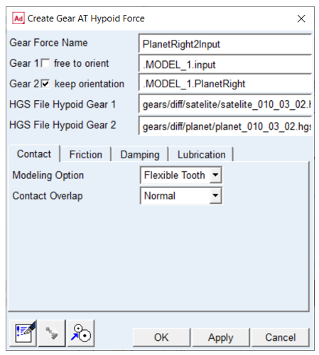
Figure 292 Create or modify gear force
For the options | Do the following |
|---|---|
Gear Force Name | Enter the Gear Force name to create or browse for existing gear force to modify |
Gear 1 toggle free to orient / keep orientation | Select the role of the Gear 1 for the gear pair assembly: ■Toggle ON to keep the orientation fixed ■Toggle OFF to free the orientation |
Gear 2 toggle free to orient / keep orientation | Select the role of the Gear 2for the gear pair assembly: ■Toggle ON to keep the orientation fixed ■Toggle OFF to free the orientation |
Hypoid Gear 1 | Select existing Hypoid Gear element |
Hypoid Gear 2 | Select existing Hypoid Gear element |
HGS File Hypoid Gear 1 | Browse for *.hgs file of Hypoid Gear prepared during meshing preprocessing step. If selected Gear FAST modeling option this field in not enabled, user has to be provide *.hgf file in Contact tab instead |
HGS File Hypoid Gear 2 | Browse for *.hgs file of Hypoid Gear prepared during meshing preprocessing step. If selected Gear FAST modeling option this field in not enabled, user has to be provide *.hgf file in Contact tab instead |
Comments | Select to display a dialog box where you can add multi-line comments to any entity to describe its purpose and function. |
Clearance check | Select to compute the clearance in the gear pair by using the solids of the gear rim. |
Orient Gears | Run clearance study of the gear pair to correctly orient the gears |
Extended definition:
Hypoid Gear elements
The Gear AT Force element is defined by Hypoid Gear 1 and Hypoid Gear 2. Gear AT Elements can be selected or created by the GUI options Pick, Browse, Guess or Create; see section Gear AT Element to learn more about the creation of a Gear AT Element.
Gear AT Mesh gives you the full control about the number of contact planes and the Mesh_density; see section Gear AT Mesh. Therefore you need to select the desired *.hgs files for the pinion and wheel.
Gear 1 / Gear 2 - free to orient / keep orientation
The Gear AT Force element is defined by Gear 1 and Gear 2. Gear AT Elements can be selected or created by the GUI options Pick, Browse, Guess or Create; see section Gear AT Element to learn more about the creation of a Gear AT Element.
The toggle keep orientation defines the gear wheel, which is fixed for the assembly and the free to orient toggle sets the gear to mesh with the other one without contact. There are various combinations possible in order to assemble closed chain gears in a differential model.
Following combinations are applicable:
Gear 1 | Gear 2 | Action | Result |
|---|---|---|---|
Keep orientation | Free to orient | Apply / OK | Gear 2 will be oriented relative to Gear 1 |
Free to orient | Keep orientation | Apply / OK | Gear 1 will be oriented relative to Gear 2 |
Keep orientation | Keep orientation | Apply / OK | no new orientation |
Free to orient | Free to orient | Hit Orient Gears Button | Both Gears will be reset to input configuration (no orientation) |
Clearance check
The icon  of Figure 292 computes the clearance in the gear pair by using the solids of the gear rim. If clearance - what should be the normal case - is found, it will be shown as depicted by Figure 301. All gear pairs in the model will be checked for the minimum clearance value. Note that solids do not include the micro-geometry.
of Figure 292 computes the clearance in the gear pair by using the solids of the gear rim. If clearance - what should be the normal case - is found, it will be shown as depicted by Figure 301. All gear pairs in the model will be checked for the minimum clearance value. Note that solids do not include the micro-geometry.Orient gears
The icon  of Figure 292 creates and loads automatically an Adams model to run clearance study of the gear pair to correctly orient gears. At the end of simulation the gears are reoriented hence the warning message about losing parametric orientation is issued in message window (Figure 293), which can be disregarded.
One can use this button to test unknown configurations without creation of forces.
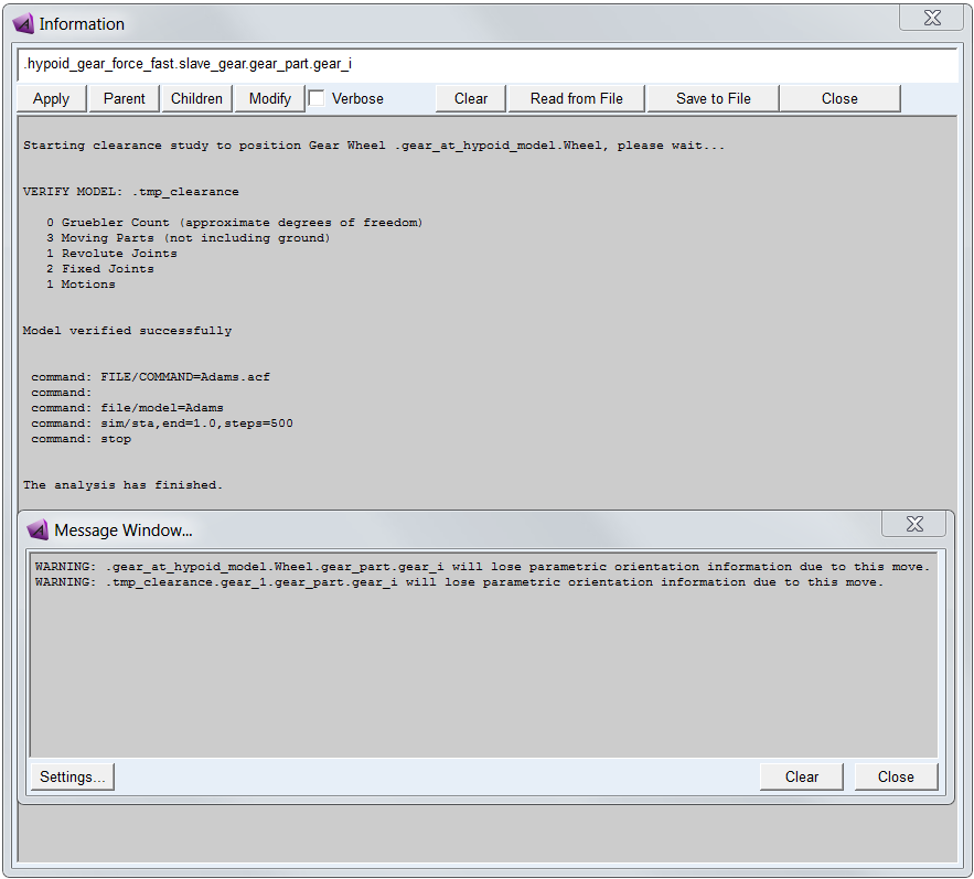
Figure 293 Analysis of gear pair clearance study
Contact
Contact algorithm implemented in Gear AT is based on numerical approach which makes possible to account for varying backlash and contact stiffness at arbitrary shaft positions and angular misalignments. It can calculate contact up to eleven teeth at a time to capture variation of gear mesh stiffness.
To define gear pair contact force there are 4 modeling options available. The first modeling option Gear FAST offers pre-computed contact formulation delivering high performance with good quality of results. It is based on results of number of contact simulations by Flexible Tooth modeling option. Other three modeling options Rigid Gear, Flexible Tooth and Full Flex Gear use an advanced surface-to-surface contact algorithm, which delivers accurate and smooth results. The tooth flanks are described by the extruded profile including parametric definition of micro geometry.
The contact model Full Flex Gear employs algorithm of Flexible Tooth contact taking the flexible wheel body deformation into account. Wheel body deformation is based on modal flexibility implemented by Adams Flex and employs modal force (MFORCE) statement. Other contact modeling options employ Adams GFORCE element.
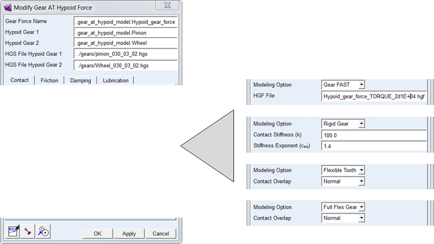
Figure 294 Contact tab of Gear Force
For the options | Do the following |
|---|---|
Modeling Option | Choose one of the following option to define the type of contact: ■Gear FAST ■Rigid Gear ■Flexible Tooth ■Full Flex Gear |
If selected Gear FAST modeling option: | |
HGF File | Browse for existing HGF file |
If selected Rigid Gear modeling option: | |
Contact Stiffness (k) | Enter the value of contact stiffness that is used to calculate the contribution of the material stiffness to the normal contact force; see Equation (28) Default: 1.0e6 |
Stiffness Exponent (cexp) | Enter the value of stiffness exponent that specifies the exponent of the force deformation characteristic. For stiffening characteristic use value of cexp>1.0; see Equation (28) Default: 1.4 |
If selected Flexible Tooth or Full Flex Gear modeling option: | |
Contact Overlap | Choose one of the following option to control relaxation of contact algorithm: ■Small (stiffer contact) ■Normal ■High (softer contact) Default: Normal |
Extended definition:
Modeling option defines the type of contact: you have 4 options to select from. The first modeling option Gear FAST offers pre-computed contact formulation delivering high performance with good quality results; for more information see Gear AT Fast Preprocessing. It is modeled with Adams GFORCE element as well as Rigid Gear and Flexible Tooth contact options.
Other three modeling options Rigid Gear , Flexible Tooth and Full Flex Gear use an advanced surface-to-surface contact algorithm, which delivers accurate and smooth results. The algorithm considers varying shaft positions and angular misalignments. The tooth flanks are described by the extruded profile including the micro-geometry. The solids for display are not used for the contact computation. The contact is checked for the left and right flanks of 5 tooth pairs.
For rigid body contact, the maximum penetration of each contact plane of Hypoid Gear 1 into the flank of Hypoid Gear 2 is used for the calculation of the corresponding contact force Fcnt as shown by Equation (28). The vector sum of all contact forces is giving the resulting contact force and torque vector per gear pair.
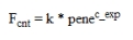 | (28) |
where:
k contact stiffness
pene maximum penetration
cexp exponent force law
pene maximum penetration
cexp exponent force law
In general, the deformation of a tooth is coming from the deformation of the wheel body, the deformation of the teeth and the 'Hertz contact'. The contribution of the 'Hertz contact' is limited compared to the two other contributions. Consequently, one has to assume, that the Stiffness Exponent is close to 1 or only slightly higher. An exponent of 1 corresponds to a linear contact stiffness.
For the Flexible Tooth contact model, the transmitted force between tooth flanks considers the flexibility of the teeth through the solution of a non-linear contact problem. The contact algorithm is of type surface-to-surface. A small relaxation by Contact Overlap is introduced for better performance; supported values are Small, Normal or High. Small overlap corresponds to stiffer contact whereas High overlap corresponds to softer contact. The effect of this additional flexibility is small compared to the flexibility of the teeth.
The contact model Full Flex Gear employs algorithm of Flexible Tooth contact taking the flexible wheel body deformation into account. Wheel body deformation is based on modal flexibility implemented by Adams Flex.
Friction
Friction of gear pair implemented in Gear AT is based on Coulomb friction model. Contribution of friction to total contact force can be turned On / Off by the Friction Model. It is computed for each contact plane of Hypoid Gear based on the relative sliding velocity at the contact point.
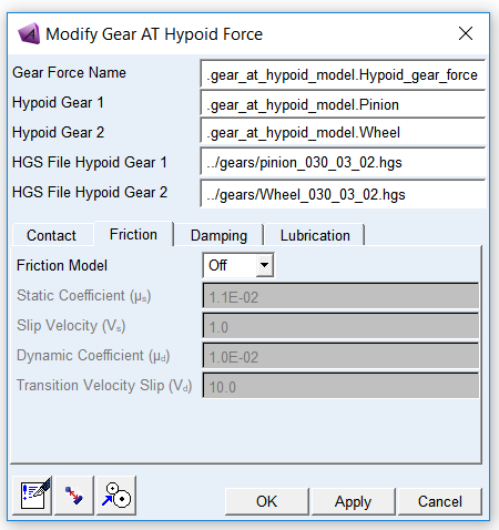
Figure 295 Friction tab of Gear Force
For the options | Do the following |
|---|---|
Friction Model | Choose one of the following options: ■Off - in this case the other fields in this card will be disabled ■On Default: Off |
Static Coefficient (µs) | Enter value of Static Friction Coefficient to define Coulomb friction Default: 1.1e-2 [-] |
Slip Velocity (vs) | Enter value of Slip Velocity to define Coulomb friction Default: 1.0 [mm/sec] |
Dynamic Coefficient (µd) | Enter value of Dynamic Coefficient to define Coulomb friction Default: 1.0e-2 [-] |
Transition Velocity Slip (vd) | Enter value of Transition Velocity Slip to define Coulomb friction Default: 10.0 [mm/sec] |
Extended definition:
The static friction coefficient is usually somewhat higher than the dynamic friction coefficient. Step functions are used for smoothing the transitions; see Figure 296. Parameter of slip velocity limits the region of sign change of the sliding velocity. The combination of very small slip velocity and high friction can reduce the performance of the integrator. You are advised to validate his selection through post-processing of the sliding velocity. Transition velocity defines the start of the region, where the dynamic friction is constant. A small difference between slip velocity and transition velocity could also lead to numerical issues of the integrator.
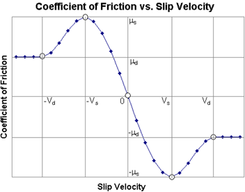
Figure 296 Friction coefficient
Under Gear FAST modeling option damping and friction are computed with simplified methods. The relative velocities in contact are evaluated only in middle plane of gear wheels. This approach can lead to noisy results under dynamic simulations; therefore adjustments for damping should be made with caution.The Friction model is reduced to 2 parametric model, with one friction coefficient and one threshold velocity.
Damping
The effects of hydrodynamic damping depend on gap height and squeeze velocities. The implemented damping force defined through Damping Rate Oil approximates hydrodynamic damping in function of the gap for each contact plane between the tooth flanks and the corresponding squeeze velocity.
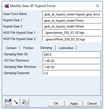
Figure 297 Damping tab of Gear Force
For the options | Do the following |
|---|---|
Damping Rate Oil | Enter value of Damping Rate Oil to define hydrodynamic damping as a function of oil squeeze velocity and actual oil film gap; see Figure 222. Default: 200.0 [kg/sec] |
Oil Film Thickness | Enter value of Oil Film Thickness per contact flank to define threshold value from which the hydrodynamic damping starts to build up; see Figure 222. Default: 1.0e-2 [mm] |
Damping Rate Structure | Enter value of Damping Rate Structure to define structural damping. It represents material damping therefore it is made proportional to the contact force. Default: 1.0e-2 [-] |
Damping Exponent | Enter value of Damping Exponent to define nonlinear hydrodynamic damping dependency on the actual oil film gap; see Figure 222. Default: 2.0 [-] |
Extended definition:
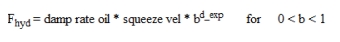
The function b defined by Equation (1) is used to define the damping; see Equation Figure 298.
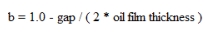 | (1) |
There is no hydrodynamic damping, when b < 0; see Equation (2)
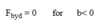 | (2) |
Hydrodynamic damping increases exponentially with decreasing oil film height. The introduction of the Damping Exponent - dexp in Equation (3) is used for this purpose; see Figure 298.
 | (3) |
In case of contact (penetration), the hydrodynamic damping force is set as shown by Equation (4).
 | (4) |
Figure 298 Function of hydrodynamic damping
Structural damping is usually a small value. The structural damping force is made proportional to the contact force as shown by Equation (33). A value of 0.01 means, that the structural damping force is 1 percent of the elastic contact force.
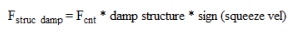 | (33) |
Lubrication
Parameters entered in the lubrication tab do not influence computation of contact force, they are used to compute wear results of minimum oil film thickness; see Advanced Results.
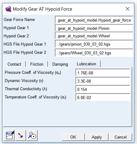
Figure 299 Lubrication tab of Gear Force
For the options | Do the following |
|---|---|
Pressure Coefficient of Viscosity (αp) | Refers to the relationship between the load placed on the oil film (pressure) at the dynamic load zone and the thickness of the oil film (viscosity) at that load, when all other factors (material, temperature, geometry, speed, load) are constant. Units for input are [mm^2 / N] |
Dynamic Viscosity (ν) | Dynamic viscosity (also known as absolute viscosity) is the measurement of the fluid's internal resistance to flow. Dynamic viscosity is product of kinematic viscosity and oil density. Units for input are [Pa * s = N * s / mm^2] |
Thermal Conductivity (λ) | Thermal conductivity (often denoted as k, λ, or κ) refers to the intrinsic ability of a material to transfer or conduct heat. Units for input are [W / m * K = N / s * K] |
Temperature Coefficient of Viscosity (αt) | Refers to the relationship between the temperature of oil at the load zone and the thickness of the oil film (viscosity) at that load, when all other factors (material, geometry, speed, load) are constant. Units for input are [1 / K] |
Extended definition:
Min_oil_film thickness (hmin) is the key parameter to evaluate linear wear coefficient (C_lT). The coefficient can be found for different pair of materials in contact from lookup tables.
The results of Min_oil_film thickness can be found in the Wearing component of request and plotted as 2D curve or 3D plot via Advanced Results. It is calculated according to PLEWE formula. The thermal correction coefficient is also considered.
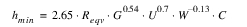 | (1) |
where:
Reqv - equivalent radius of curvature
G - elasticity coefficient
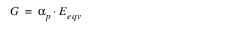 | (2) |
U - velocity coefficient
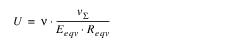 | (3) |
W - load coefficient
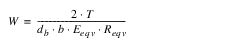 | (4) |
C - thermal correction
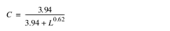 | (5) |
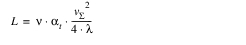 | (6) |
where:
αp - pressure coefficient of viscosity
αt - temperature coefficient of viscosity
λ - thermal conductivity
ν - dynamic viscosity
vΣ - sum of tangent velocities
Eeqv - equivalent module of elasticity
T - Torque
db - base diameter of pinion
αw - working pressure angle
b - width of contact
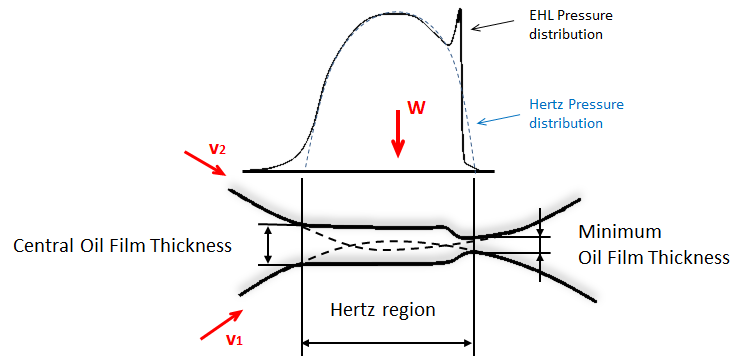
Figure 300 EHL film thickness behavior