Using the Adams View Controls Toolkit
Learn about the Adams View Controls toolkit, which provides simple linear control and filter blocks to quickly build PID controls, prefilters, or other linear continuous time-element representations:
Process for Building Controls Blocks and Prefilters
Follow the process below for building controls blocks and prefilters into your Adams View models using the Adams View Controls Toolkit:
1. Draw a picture with your model and the controls and filters you want to add.
Step 1 - Draw a Picture
Before adding filters and controls to your model, draw a block diagram showing the model, the inputs to the control and filter blocks from the model, and the outputs from the control and filter blocks to the model. A graphical representation of a typical block diagram to use for adding filters and controls is shown in the figure below.
.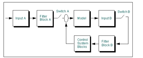
Example Block Diagram for Using Control and Filter Blocks
The inputs to the control and filter blocks that you need to diagram include:
■Time-based forcing functions, which might be considered "external inputs" such as Input A in the figure above.
■Feedback loops, which might be considered "internal inputs" or closed, control loops such as Input B in the figure above.
The outputs from the control and filter blocks that should be in your diagram include:
■Filtered measures of your model that you want to track for display or plotting purposes.
■Outputs from your model that are used as inputs to the control blocks you will be adding.
Consider adding switches to your models at places where you might want to "open the feedback loop," either for debugging your model or for seeing the change in performance that controls provide.
Once you have identified the inputs and outputs for the control and filter blocks, you are ready to create the necessary blocks and connect them together and to the model.
Step 2 - Create All Input Blocks
You must first create an input block to connect to other control blocks. For example, if you want to use a displacement from your model as an input to your control block, you must first create an input block to set up the signal for the control block.
Step 3 - Create Other Control and Filter Blocks and Connect Them
Once you have created the input blocks, you can then create controls blocks and specify how they interconnect with each other and input functions. The input to a control or filter block must be given as the name of another existing control block or input block. The output of controls blocks can be referenced in function expressions. Each control block maintains a state variable value. The name of the Adams state variable can be found using the Database Navigator for a PID block (see Picture of Database Navigator with PID Block). This value is then referenced in elements, such as forces, by simply typing in the element name as the function expression. See Picture of referencing element.
Step 4 - Check All Input and Output Connections
Available Controls Blocks
Learn about the different controls blocks available in Adams View Controls Toolkit:
Input Function Block
Input function blocks are needed wherever a control or filter block does not receive its input from another control or filter block. This includes external time functions that need to be passed into a block, as well as measures of your model that represent error signals to pass into a block.
An input function block takes any valid solver expression as its input. The input function block is a valid controls block to reference as the input to any other controls block.
Summing Junction Block
Summing junction blocks are used to add or subtract the outputs from other standard blocks. You can select whether the positive or negative value of an input to a summing junction is used by single clicking on the +/- sign button.
A summing junction block takes any valid controls block output as its input. Specify the assembly name of any controls block, including input function blocks, in either the Input 1 text box or the Input 2 text box.
Gain, Integrator, Low-pass Filter, and Lead-lag Filter Blocks
Gain, integrator, low-pass filter, and lead-lag filter blocks are used to create the s-domain (Laplace domain) representation of basic linear transfer functions. For each of these blocks, the block gain or the filter coefficients are specified as an Adams View scalar real value. You can parametrize this constant with an Adams View real design variable to quickly study the effect of varying the bandwidth or gain of the associated block.
Specify the assembly name of any controls block as the input field to these blocks.
User-Defined Transfer Function Block
The user-defined transfer function block is used to create general rational polynomial blocks by specifying the polynomial coefficients. Coefficients are specified in the order n0, n1, n2, n3,…. for the numerator where the underlying polynomial representation is given as n0+n1x1+n2x2+n3x3+… and similarly for the denominator. Specify the assembly name of any controls block as the input field to this block.
Second-Order Filter
The second-order filter block is used to create a second-order filter by specifying the undamped natural frequency and the damping ratio. You can parametrize the undamped natural frequency or damping ratio constant with an Adams View real design variable to quickly study the effect of varying the frequency or damping ratio of the associated block.
PID Controller
The PID controller is used to create a general proportional-integral-derivative control block. Two inputs are necessary for this block: the proportional input and the derivative input. You must specify the derivative state for input to this block that is consistent with the proportional state. For example, if the proportional input is the measured x position of a part, the derivative input should be the linear velocity in the x direction.
This block automatically creates the integrated state of the proportional input for use as the integrated input. You can parameterize the P, I, and D gains of this block with Adams View real design variables to quickly study the effect of changing control gains.
Switch
The switch is a convenient means to "zero" the signal into any block. Connect the switch at a point in the feedback loop to quickly see the change from open loop control to closed loop control. The switch takes any control block as its input.
Creating Controls Blocks
To create a block in the Adams View Controls Toolkit:
1. Click the Elements tab. From the Controls Toolkit container, click the Controls Toolkit tool .
.
. or
(Classic interface) From the Build menu, select Controls Toolkit.
The Create/Modify Standard Controls Block dialog box appears.
2. Select an icon representing the type of block that you want to create. The choices in the Create Controls Block dialog box change to those for creating the selected control block. Learn about the different types of blocks.
3. Enter the block name, all required inputs, and all required parameters. Inputs to controls blocks are required to be existing controls blocks, with the exception of the input function block. Learn about the options for each control block:
4. Select OK.
Modifying Controls Blocks
You modify blocks in the Adams View Controls Toolkit by selecting their assembly name in the Database Navigator.
Checking Block Connections
In the Adams View Controls Toolkit, you can verify that all control and filter blocks are properly connected. When you verify the connections, Adams View checks that all blocks have defined inputs and then checks that all block outputs are referenced either in other blocks or as inputs to your model.
To check block connections:
 on the
 Creating Custom Blocks
Adams View defines each type of control in the Adams View Controls Toolkit as an assembly. Each time you use a controls block of a particular type, you create an instance of that assembly type. Using the Database Navigator, you can find the controls assemblies as well as other assemblies defined under the Adams library.
The controls block assembly definition combines Measures, Adams View Design variables, Adams Solver variables, Adams Solver transfer functions, and Adams Solver arrays into one database object. When Adams View creates a control block instance, it creates all the appropriate variables, functions, and arrays underneath that block, all with that block name.
You can create your own control blocks by first creating an assembly definition, and then adding your assembly to the controls library. Your control blocks can have any set of equations that you require by adding the appropriate Adams Solver functions and variables to the block definition.
Plant Inputs and Outputs
Plant output defines the set of measured outputs from the system and Plant input defines a set of inputs to the mechanical system. Adams Linear linearizes the system equations to the following form:
where:
■x is the linearized system state array.
■u is the array of system inputs defined by plant input.
■y is the array of system outputs defined by plant output.
This form is commonly referred to as the state-space form of the system equations in control theory. Adams Solver outputs the A, B, C, and D matrices for use in a control-system design or any other linear system analysis software. If only the A matrix is required, plant input and plant output are not necessary.
Ways to Use Plant Input and Output
The plant outputs with the plant inputs, variables, arrays, transfer functions, linear state equations, and general state equations define the interface between Adams and control design and analysis packages such as MATRIXx and MATLAB.
As shown below, plant inputs and outputs act as socket for input and output to your controller, organizing the variable wires.
Adams Linear uses plant inputs and outputs to identify which variables to consider system inputs and outputs when generating state matrices. A control design program can use these matrices to design a controller for the system. The resulting controller can then be included in the model using variables, arrays, transfer functions, linear state equations, or general state equations. See the LINEAR command in the Adams Solver online help.
Creating Plant States
(Adams Solver (C++) only. Learn about switching solvers with Solver Settings - Executable dialog box help.)
Adams Linear requires a minimum representation of the system to generate the state matrix from which eigenvalues can be computed. For non-stationary systems, the state matrix is a function of the states used to linearize the system. In Adams Solver (C++), you can define a set of states that are to be used in the linearization scheme. You can specify as many states as there are degrees-of-freedom. If a smaller set of states are provided, then the system will fill in by choosing a set of internally available states for the ones that were not explicitly specified. If too many states are specified, Adams Solver identifies and discards the redundant states.
Plant states are a list of variables. The variables contain expressions that specify the states that are to be used in linearizing the system. Plant state objects are defined in the model. The LINEAR command can instruct Adams Solver (C++) to use a specific plant state object for generating the linear model. A model can contain any number of plant state objects. You can use any one of them with the LINEAR command.
■For more information, see the Adams Solver (C++) LINEAR command.
■For theoretical details, see the white paper in Simcompanion Knowledge Base Article KB8016460.
■For an example of using PSTATE, see Simcompanion Knowledge Base Article KB8016414.
To create a plant state:
1. Click the Elements tab. From the Data Elements container, click the Plant State tool .
.
. or
(Classic interface) From the Build menu, point to Data Elements → Plant → Plant State, and then select New.
2. Enter the name you want assigned to the plant state.
3. In the Adams Id text box, assign a unique ID number to the plant state.
4. In the Comments text box, add or change any comments about the plant state to help you manage and identify the plant state.
5. Enter the list of variables. To help you create a variable for a plant state object, select Create State Variable for Plant State. You can set values for the state variables in the Create State Variable for Plant State dialog box.
6. Select OK.
To run a linear modes simulation using the plant state object:
1. Set the solver to Adams Solver (C++).
2. In the Interactive Simulation palette, right-click the Compute Linear Modes tool  , and then select the Compute Linear Modes with Pstate tool
  .
.
, and then select the Compute Linear Modes with Pstate tool . The Compute Linear Modes dialog box appears.
3. Enter the plant state object you created and the reference marker.
4. Select OK.