Parts
Parts define the objects in your model that can have mass and inertia properties and can move. All forces and constraints that you define in your model act on these parts during a simulation. The next sections explain more about parts:
Types of Parts
Adams View provides you with four different types of parts that you can create:
■Flexible bodies - Basic Adams View provides you with the ability to create Discrete Flexible Link. For more functionality, you can purchase Adams Flex. For information on purchasing Adams Flex, see your MSC sales representative, and for information on using Adams Flex, refer to Adams Flex online help.
In addition, Adams View provides a ground part that is already created for you.
About the Ground Part
The ground part is the only part in your model that must remain stationary at all times. Adams View creates the ground part automatically when you create a model. You can also define a new or existing part as the ground part. The ground part does not have mass properties or initial velocities and does not add Degrees of freedom into your model.
The ground part acts as the global coordinate system that defines the global origin (0,0,0) and reference frame about which you create your model. You cannot specify its position. You can add geometry to the ground part.
In addition, by default, the ground part also acts as the inertial reference frame with respect to which all of the part velocities and accelerations are calculated. You can also select another part as the inertial reference frame. You can select another part through the Command Navigator.
Note that although the ground part is the only part in your model that must remain stationary at all times, you can move the geometry and constraints attached to the ground part. Since geometry and constraints are tied to markers, you can use the Select List Manager to select all the markers on ground and then translate and rotate the ground entities with the rest of your model.
Learn about Defining a New Ground Part.
Local Coordinate Systems
As you create parts, Adams View assigns a coordinate system to each part, known as its local coordinate system. A part’s local coordinate system moves with the part and its original position defaults to that of the global coordinate system.
The local coordinate system is a convenient way to define the position and location of objects. Adams View also returns Simulation results, such as the position of a part, as the displacement of a part’s local coordinate system with respect to the global coordinate system. It returns object results, however, as the displacement of a part’s center of mass relative to the global coordinate system.
Degrees of Freedom
Each rigid body that you create can move within all Degrees of freedom; a point mass can move within three translational degrees of freedom. You can constrain the movement of parts by:
■Adding them to the ground part, which means they are fixed to the ground and cannot move in any direction. Each time you create geometry, Adams View gives you the option to add it to ground, create a new part, or add it to an existing part.
■Adding constraints, such as joints, to define how the parts are attached and how they move relative to each other.
Naming Conventions
As you create parts, Adams View automatically generates names for them based on their type and the number of objects of that type in your model. For example, when you create a point mass, Adams View names it POINT_MASS_1. For all rigid bodies, except points and coordinate system markers, Adams View uses the name PART regardless of the type of geometry. For example, if you create a box, Adams View names it PART_1. When you create a second box, Adams View names it PART_2, and so on. You can rename your parts. Learn about Renaming Objects Through Menu Commands.
Rigid Bodies
The most common type of part in your model is a Rigid body. Adams View provides a library of geometry that you can use to create rigid bodies. A part can be made up of many different geometric objects. There are two types of geometry that you can use to create rigid bodies.
Each time you create geometry, you can select to do one of the following:
■Create a new part containing the geometry.
■Add the geometry to an existing part.
■Add the geometry to ground. You add geometry to ground if the geometry does not move or influence the simulation of your model. For example, if you are simulating a car driving around a race track, the geometry that defines the race track can be added to ground. (You can also fix parts temporarily to ground using a fixed joint.
In addition, you specify the location of the geometry in space. You can select to define the location of the geometry:
■Graphically, by picking locations on the screen or by selecting an object on the screen that is at the desired location.
■Precisely, by entering coordinate locations.
Also See Geometric Modeling Palette and Tool Stack to learn more about creating rigid body geometry.
Modeling Two-Dimensional Body Using Planar Option
Adams Solver (C++) only
After you create a rigid body, you can identify it as planar (as having only three degrees of freedom (DOF)) instead of creating a planar joint (see Planar Joint Tool). The three DOFs are global x and y translations and a rotation about the global z-axis. You can think of the body as a regular three-dimensional body with a built-in planar joint. Unlike a body and a planar joint pair, however, which combines to add 18 equations to an index-3 dynamic analysis in Adams Solver, the planar body only adds six equations.
Notes: | ■Using planar parts does not limit your use of three-dimensional contacts. If you can simplify your contacts to two-dimensional representations, however, you will usually realize speed improvements. ■A planar body is implicitly constrained to move in a plane at a fixed global value of z. Any force applied to the planar part in the global z direction is discarded. The same applies to torques about the global x- and y-axes. It is not possible to measure the reaction forces required to constrain the planar part to stay in plane. If such forces are desired, you must substitute the equivalent part and planar joint combination. |
To set a part as planar:
1. Create the three-dimensional rigid body.
3. Set Category to Name and Position.
4. At the bottom of the dialog box, select Planar.
5. From the option menu that appears, select the plane in which the planar part will move. The default is for the planar part to move in the global xy plane.
6. Select OK.
Parameterization
As you create rigid bodies in your model, you can define them so that the location or orientation of one object affects the location or orientation of another body. This is called parameterizing your model.
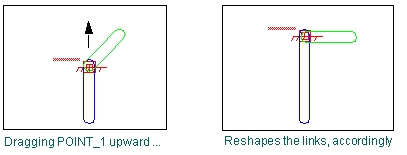
Parameterizing your model simplifies changes to your model because it helps you automatically size, relocate, and orient objects. For example, if you parameterize the geometry of two links to the location of a point, when you move the point, the link geometry changes accordingly, as shown in the figure below.
Example of Parameterizing Locations
The ways in which you can build parameterization into your model while creating rigid bodies include the following:
■Attach objects to points so that when you change the location of the points, the body locations and orientations update accordingly.
As you create a point, Adams View gives you the option to attach other nearby objects to the point. The help that explain how to create points also explain how to attach objects to them.
■Define design variables to represent values of your rigid body geometry, such as the length or width of a link. You can create design variables for any values you specify for a rigid body. Design variables are needed when you run tests on your model, such as design studies. Learn about Using Design Variables.
■Create expressions that calculate the values of your rigid bodies, such as the length or width of a box. You can specify expressions for any values you specify for a rigid body geometry. For more information on creating expressions, see Adams View Function Builder online help.
You can also parameterize your model after you build it. For more information on parameterization, see Improving Your Model Designs
Before You Begin
Before you begin creating the parts of your model, you might want to take some time to set up your modeling environment and learn some drawing and placement techniques. To help you place parts accurately, do the following:
■Turn on the Working grid so that the points snap to a grid. In addition, Adams View draws objects parallel to the current working grid so by displaying it you can better see how your objects are being drawn. Learn about Setting Up the Working Grid.
■Display the Coordinate window so that you can view the coordinate values as you place points. Learn about Working with the Coordinate Window.
■Be sure to set the current units to those required for your model. Learn about Setting Default Coordinate System.
■Review the different tools for drawing and placing objects in Tools and Techniques.