ViewFlex
Dialog boxes where you can set orientation dependencies Shared Dialog Box
Transforms a rigid part to an MNF-based flexible body using embedded finite element analysis where a meshing step and linear modes analysis will be performed.
For the option: | Do the following: |
|---|---|
Part to be meshed | Pick the part to be meshed. |
Material | Browse and select the material to be used for the flexible body. |
Number of Normal Modes | Enter the number of modes for the flexible body. |
Stress Analysis | Check if you would like stress information to be generated with the flexible body. |
Strain Analysis | Check if you would like strain information to be generated with the flexible body. |
Manual Replace | Select to only generate a flexible body, not automatically replace the rigid body for the flexible body in the model. ■Manual Replace = Off : Viewflex will automatically replace the part with flexible body by transferring all connections from rigid body to flexible body. This will deactivate the rigid part and make it invisible. ■Manual Replace = On: Viewflex will not automatically replace the part and both rigid and flexible body will be shown. You need to manually create the connections on the flexible body. |
Advanced Settings
This will allows you to control the details of creating the flexible body.
For the option: | Do the following: |
|---|---|
Load AFI File | ViewFlex writes information about centerline, cross section, attachment points, and flexible elements to a ViewFlex input (AFI) file. See Using AFI Files for more information. |
Flexbody Type | There are three methods for defining flexible bodies in ViewFlex and integrating them into Adams. ■Extrusion ViewFlex enables the generation of a flexible body automatically that is defined as a geometric extrusion of a section profile along a generic centerline. Using this option, rigid parts previously defined on the model to generate flexible bodies are not needed. See Generating Parametric Extrusions for more information. ■Geometry This provides different options than in the Extrusion Method. In the upper part of the window you can select the existing geometry, whereas the lower section is for defining the mesh properties. See Creating Flexible Bodies from Existing Solid Geometry for more information. ■Import Mesh The external mesh (BDF or DAT format) can be imported into ViewFlex to generate a flexible body. After importing the mesh you can set all the options for elements properties, attachments and secondary nodes to create the flexible body. See Creating Flexible Bodies from Imported External Meshes for more information. |
FlexBody Name | Selected flexible body name will be displayed. |
If you selected Extrusion following options available: | |
Centerline | To control the type of interpolation between the different parts of the centerline. This will displays a data table in which to define the centerline, along with the extrusion to be created. This has following options: ■Interpolation ■Linear: Linear interpolation ■Cubic: Cubic interpolation (may require more than two reference markers to capture curvature events). ♦The Auto Align option enabled. ■None: No interpolation is used ■Pick/Browse Coord Reference: Select the coordinate system for which, if available, the orientation appears in the data table. ■View Centerline Geometry: This will allow you to view the centerline geometry. For more details see section Defining the Centerline. |
Section | You have the options to specify the section to extrude. ■Section Type ■Elliptical: You provided with the options for defining an ellipse. ■Generic: You provided with the options for defining a generic section. For more details see section Modeling the Section. |
Mesh/Properties | Displays the general material and mesh properties. ■Element Type: Indicates what type of elements are to be generated. ■Shell Quad: Creates shell quad elements. ■Solid Hexa: Creates solid hexa elements. ■Solid Wedge: Creates solid wedge elements (valid for complex sections). ■Element Size: Enter the average edge length of the element. ■Nominal Thickness: Enter the average thickness of the element ■Normal Direction: X, Y, Z, -X, -Y, -Z ■Stress/Strain Analysis: Check if stress/strain information is to be generated for the flexible body. ■Shell Stress/Strain Layers: Select the layer on which you want the stress and/or strain calculated ■Top ■Middle ■Bottom For more details see Generating Parametric Extrusions. |
Attachments | Points at which the flexible body will be attached to other bodies. See section Defining Attachment Points in Parametric Extrusions for information. |
If you selected Geometry following options available: | |
Mesh/Properties | You have the following option under this properties: ■Element Type: Indicates what type of elements are to be generated. Available options are point, line, area or volume elements. ■Solid: Creates solid elements. ■Shell: Creates shell elements. ■Element Shape ■Tetrahedral - Creates tetrahedral solid elements. Card: CTETRA. Linear: CTETRA4, Quadratic: CTETRA10 The following Element shapes appear when Shell Element Type is selected ■Triangle - Creates triangular shell elements. Card: CTRIA. Linear: CTRIA3, Quadratic: CTRIA6 ■Quadrilateral - Creates quadrilateral shell elements. Card: CQUAD Linear: CQUAD4, Quadratic: CQUAD8 ■Element Order: Indicates what order of elements are to be generated. Available options are linear and quadratic. The specified element order must be compatible with the element order used in previously meshed adjacent regions. ■Linear: Sets linear element order for first-order elements ■Quadratic: Sets quadratic for second-order elements. ■Element Specification ■Auto: Uses an automatic scale factor to determine the element size based on the selected part's dimensions. ■Size: After entering the average edge length of the element, ViewFlex asks you to input the element's median and minimum side size (using automatic mesh refining, where required by the geometry to mesh). ■Edge Shape: Indicates whether higher order element should be generated with straight or curved boundary edges. ■Straight: All mid-side nodes will be positioned at the average coordinate of the end nodes. ■Curved: Mid-side nodes on boundary geometry will be projected onto the geometry resulting in curved element edges. ■Mixed: Edges will be curved except when such curving would result in an invalid element (negative Jacobian). ■Element Size: Enter the average edge length of the element. This option will be available upon selecting “Size” from Element Specification options. |
■Minimum Size ■Absolute minimum element size. The mesh generator uses this size to cap off the refinement when doing curvature based refinement. If the curvature factor specifies a element edge length which is smaller than the minimum element size, the edge length is capped off by using the minimum element size. This avoids over refinement in areas of high curvatures. | |
■Growth Rate ■The parameter 'growth rate' is a mesh parameter to control the rate of size transition between adjacent elements. It is the desired maximum length ratio between 2 adjacent tetrahedral edges. This parameter is mainly used to produce coarser elements in the interior of a solid and reduce the number of tet-elements on the solid. When meshing a solid with curvy faces, the tet-elements on the solid faces have to follow the shape of geometry of the surfaces, and their sizes are generally small. If the growth rate is close to 1.0, the small mesh sizes will be propagated from the solid boundary to the interior of solid and the number of elements may be very big; if the growth rate is bigger, the mesh size will increase gradually from the solid boundary to the interior of solid, as a result, the number of elements will be reduced. ■Shell Thickness: Enter the thickness of shell elements for computing mass and stiffness properties. | |
■Angle Per Element ■The parameter "angle-per-element" is a curvature-based mesh size control parameter which is the max-allowed subtended angle of an element-edge on a curved surface. It is used to define local mesh density at each point of a surface. ■For a point P on a curved surface, we use the following way to define subtended angle of an element-edge E in the neighborhood of P and define local mesh density at the point P: ♦First, we calculate the principal curvatures at the point P. Then use the reciprocal of the max principle curvature as radius and the center of max principle curvature as center to define an osculating circle that passes through the point P. The element-edge E is considered a chord of the osculating circle. The subtended angle of element-edge E is defined as the subtended angle of the chord from the center of the circle. ♦The local mesh density D at P is calculated as the length of the chord whose subtended angle = angle-per-element. The length of an element-edge in the neighborhood of P should be equal or smaller than the local mesh density D. If angel-per-element is fixed, the local mesh density D is inversely proportional to the max principal curvature at P; if max principal curvature is fixed, the local density D increases as angle-per-element increases. Example: If angle-per-element = 30 degree and there is a circular hole of a surface, we expect that at least 12 (=360/30) element-edges along the hole. 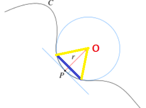 Where: ■P: a point on surface, Circle: the osculating circle, C: a curve on a surface, O: the center of osculating circle, r: the radius of the osculating circle which = 1.0/mpc, where mpc is the max principle curvature at point P. ■Blue line segment E: An element-edge in the neighborhood of P. ■Yellow line segment: Connecting an end point of the E to the center of osculating circle The subtended angle of element-edge E is the angle formed by two yellow-line-segments. It is controlled by angle-per-element | |
■Stress Analysis Enables stress recovery to be available in Adams PostProcessor. ■Strain Analysis Enables strain recovery to be available in Adams PostProcessor. ■Shell Stress/Strain Layers: Select which layer to recovery stress and/or strain ♦Top ♦Middle ♦Bottom ■Normal Direction: X, Y, Z, -X, -Y, -Z ■Collapse small edges: If checked small edges or features will collapse to zero in meshing. ■Curvature Based Scaling: ON or OFF When this option is ON the mesher uses the geometry (curve or surface) curvature to automatically provide mesh grading and smoother mesh transition. The mesh will be more uniform if this option is turned OFF as no grading is done. ■Advanced Options: This option will be activated upon by importing SHELL type geometry. It will list the translation and rotation data of the meshed geometry. Selecting "Get from Model" fills the text boxes with the current location and orientation of the selected geometry automatically. | |
Attachments | After creating the geometry attachment points need to be defined. ■Selection Type ■Node IDs ♦Pick Nodes ♦Transfer IDs ■Spherical ♦Radius ♦Transfer IDs ■Cylindrical ■Radius ■End Location ■Symmetric ■Transfer IDs ■Closest nodes ♦Number of nodes ♦Transfer IDs ■Solid feature ■Vertex ■Edge ■Surface ■Pick ■View part only Rigid Body Element (RBE) connected by attachment nodes can be previewed by clicking on RBE toggle button and Mesh Preview can be hidden by clicking off Mesh toggle button. ■Show/Hide ■Mesh ■RBE See section Defining Attachment Points in Existing Solid Geometry for information. |
Mesh Preview | Select to preview a mesh of the selected geometry. For more details see Creating Flexible Bodies from Existing Solid Geometry. |
If you selected Import Mesh following options available: | |
Mesh/Properties | ■Shell Thickness: Enter the thickness of shell elements for computing mass and stiffness properties. ■Normal Direction: X, Y, Z, -X, -Y, -Z ■Stress Analysis: Check if stress information is to be generated for the flexible body. ■Strain Analysis: Check if strain information is to be generated for the flexible body. ■Shell Stress/Strain Layers: Select the layer on which you want the stress and/or strain calculated ■Top ■Middle ■Bottom For more details see Creating Flexible Bodies from Imported External Meshes. |
Attachments | Points at which the flexible body will be attached to other bodies. See section Defining Attachment Points after Importing an External Mesh for information. |