Applied Forces
Applied forces are forces that define loads and compliances on parts so they move in certain ways. Adams View provides a library of applied forces that you can use. Applied forces give you a great deal of flexibility, but they require work to model simple forces. Instead of using applied forces, you may want to consider using the flexible connectors, which model several commonly used force elements, or special forces, which provide environmental and complex forces.
Applied forces can have one, three, or six components (three translational and three rotational) that define the resultant force. For example, a single-component force or torque defines the force using a single component, while a multi-component force or torque defines the force using three or more components. The following figure shows all six possible force components associated with a particular coordinate system’s x-, y-, and z-axes.
As you create applied forces, you specify:
■Parts to which the force is applied and its direction - You can apply the force to two parts or to one part and ground. Adams View creates a marker on each part. The first part you select is the action body and receives the force action. The second part you select is the reaction body and receives the force reaction. If you specify one part and ground, the reaction force is on the ground part, and, thus, has no effect on your model.
■Characteristic, which defines the magnitude of the force. You can specify:
♦Constant force - You enter a constant force value. When Adams View creates the force, it uses the value you enter as the force function. When you modify the force, you can change the value or enter a function expression or parameters to a user-written subroutine as explained for the Custom option below.
♦Bushing or spring-like - Adams View creates a function expression defining the linear stiffness and damping forces based on the stiffness and damping coefficients that you specify.
♦Custom - You define the magnitude of the force as a function of any combination of displacements, velocities, other applied forces, user-defined variables, and time. You can write a function expression or enter parameters to be passed to a User-written subroutine (for example, SFOSUB or VFOSUB) that is linked into Adams View. You define the constitutive equation for the force applied to the action body. Adams View evaluates the reaction forces on the reaction body. You can also specify an alternative library and name for the user subroutine. Learn about specifying routines with ROUTINE Argument.
Adams View evaluates the signed magnitude of the force and applies it to the selected body or bodies.
Single-Component Forces
To create a single-component force:
1. From the Create Forces tool stack or palette, select either:


2. In the settings container, specify the following:
■The number of parts and the nature of the force direction. You can select the following:
♦Space Fixed
♦Body Moving
♦Two Bodies
■How you want the force oriented. You can select:
♦Normal to Grid - Lets you orient the force normal to the current Working grid, if it is displayed, or normal to the screen.
♦Pick Feature - Lets you orient the force along a direction vector on a feature in your model, such as along an edge or normal to the face of a part.
■The characteristics of the force. You can select the following:
♦Constant force/torque - Enter a constant force or torque value or let Adams View use the default value.
♦Spring-Damper - Enter stiffness and damping coefficients and let Adams View create a function expression for damping and stiffness based on the coefficient values. (Not available when you are using the Main toolbar to access the force tool.)
♦Custom - Adams View does not set any values for you, which, in effect, creates a force with zero magnitude. After you create the force, you modify it by entering a function expressions or parameters to a SFOSUB User-written subroutine that is linked to Adams View. You can also specify an alternative library and name for the user subroutine. Learn about specifying a routine with ROUTINE Argument.
3. Do one of the following depending on whether you are creating a single-component force or torque:
■For a single-component force, select the action body. If you selected to create a torque between two parts, select the reaction body and then select the points of application on the two bodies. Be sure to select the point of application on the action body first.
■For a single-component torque, select the action body. If you selected to create a torque between two parts, select the reaction body and then select the points of application on the two bodies. Be sure to select the point of application on the action body first.
4. If you selected to orient the force along a direction vector on a feature, move the cursor around in your model to display an arrow representing the direction along a feature where you want the force oriented. When the direction vector represents the desired orientation, click.
Modifying Single-Component Forces
The following procedure explains how to modify the following for a single-component force:
■Force direction, if only one part is affected.
■Action body to which the force is applied. If you created the force between two parts, you can also change the reaction body. You cannot change a force created on one part and ground to a force created between two parts because the direction methods are not compatible. You’ll have to delete the force and create it again.
■Force magnitude.
To modify a single-component force:
2. Set the following in the dialog box, and then select OK.
To: | Do the following: |
|---|---|
Set the number of parts affected and the direction of the force | Select either: ■On One Body, Fixed in Space - Sets the force direction so it is applied to a part. The force direction is fixed on ground. ■On One Body, Moving with Body - Sets the force so it is applied to a part. The part defines the direction of the force. ■On One Body, Moving with Other Body - Sets the force so it is applied to a part. A second part (the direction part) defines the direction of the force. ■Between Two Bodies - Creates a force between two parts. One of the parts can be ground. You cannot change a force on one part to a force defined between two parts or the reverse. You can, however, change a torque on one part to a torque on two parts or the reverse. |
Set the bodies used in defining the force | Change the values in the following text boxes as necessary. The text boxes available depend on how you defined the direction of the force. ■Body - Change the action body to which the force is applied. ■Action Body - For a force defined between two parts, change the action body to which the force is applied. ■Reaction Body - Change the body that receives the reaction forces. ■Direction Body - Change the body that defines the direction of the force if you selected the direction option, On One Body, Moving with Other Body. Tips on Entering Object Names in Text Boxes. |
Change the force function defining the magnitude of the force | Set Define Using to how you will define the force. Select: If you selected Function, enter the following in the Function (time) text box that appears: ■Constant force value ■Function expression To enter a function expression, next to the Function text box, select the More button  to display the Function Builder. to display the Function Builder.■Subroutine to define using a User-written subroutine SFOSUB or you can specify an alternative library and name for the user subroutine in the Routine text box. Learn about specifying routines with ROUTINE Argument. If you selected Subroutine for Define Using, enter the parameters to be passed to a user-written subroutine and its ID. Entering an ID is optional. |
Force Display | Set whether you want to display force graphics for one of the parts, both, or none. By default, Adams View displays the force graphic on the action body for single-component forces. |
Specifying Force Direction for Single-Component Forces
When you create a single-component force, you have three options for specifying the number of parts affected and the direction of the force:
■Space fixed - Applies the single-component force to one part, or action body, that you select. Adams View automatically applies the reaction force to ground. You specify a direction for the force. The direction never changes. It remains fixed in space during the simulation, even if the action body moves because the marker used to define the force direction is attached to the ground part.
■Body moving - Applies the single-component force to one part, or action body, that you select. Adams View automatically applies the reaction force to ground. You specify a direction for the force. The direction can change during the simulation because the coordinate system marker used to define the force direction is attached to the action body. You can attach the direction marker to a different part when you modify the force.
■Two bodies - Applies the single-component force to two parts that you select, at two locations that you select. Adams View defines the direction based on the line of sight between the two locations you selected.
Multi-Component Forces
To define more complex forces, you can use multi-component forces. Multi-component forces apply translational and/or rotational force between two parts in your model using three or more orthogonal components. The following lists the different types of multi-component forces:
A multi-component force applies an action force to the first part you select, which is called the action body. Adams View automatically applies a corresponding reaction force to the second part you select, which is called the reaction body. If you define the force characteristics as bushing-like, Adams View generates equations to represent a linear spring-damper in the specified component directions.
To define the points of application of the multi-component force, Adams View creates a marker for each part. The marker belonging to the action body is the action marker, and the marker belonging to the reaction body is the reaction marker. Adams View keeps the reaction marker coincident with the action marker at all times. The reaction marker is often referred to as a floating marker because its location is not fixed relative to the body to which it belongs. Action and reaction markers are also referred to as I and J markers.
Adams View also creates a third marker called a reference (R) marker that indicates the direction of the force. You define the orientation of the reference marker when you create a multi-component force. You can align the marker to the working grid, if it is turned on, or to the global coordinate system. You can also orient the marker using any feature in your model, such as along an edge of a part.
Example of Action and Reaction Force Movement
The following figure illustrates the movement of reaction forces and the placement of the reference marker. The figure shows a ball bouncing on a board. As the ball bounces, its location changes relative to the board. The reaction forces applied to the board also change location because the reaction (J) marker moves with the ball. The reaction forces applied to the board do not change direction because the reference (R) marker belongs to the stationary board.
Tip: | You can use the Info command to see the markers that Adams View creates for a multi-component force. You can also see the markers when you modify the force. Learn about Displaying Object Information and Accessing Information Window. |
Total Force Equations
For a six-component general force and a three-component force, the total force that Adams Solver supplies is the vector sum of the individual force components that you specify. Its magnitude is the square root of the sum of the squares of the three mutually-orthogonal force components:
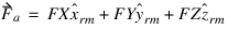
where:
■ is the action applied to the action body.
is the action applied to the action body.■FX is the user-defined function defining the magnitude and sign of the x-component.
■FY is the user-defined function defining the magnitude and sign of the y-component.
■FZ is the user-defined function defining the magnitude and sign of the z-component.
 is a unit vector along the + x direction of the
 ■ is a unit vector along the + y direction of the reference marker.
is a unit vector along the + y direction of the reference marker.■ is a unit vector along the + z direction of the reference marker.
is a unit vector along the + z direction of the reference marker. The values of the reaction forces are:

where r is the reaction force applied to the reaction body. If you apply the force to a part and ground, Adams Solver does not calculate the reaction forces.
Total Torque Equations
For a Six-component general force and a Three-component torque, the magnitude of the torque is the square root of the sum of the squares of the magnitudes of the three mutually orthogonal torque components, such that:
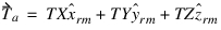
where:
■ is the action applied to the action body.
is the action applied to the action body.■TX is the user-defined function defining the magnitude and sign of the x component according to the right-hand rule.
■TY is the user-defined function defining the magnitude and sign of the y component according to the right-hand rule.
■TZ is the user-defined function defining the magnitude and sign of the z component according to the right-hand rule.
 is a unit vector along the + x direction of the
 ■ is a unit vector along the + y direction of the reference marker.
is a unit vector along the + y direction of the reference marker.■ is a unit vector along the + z direction of the reference marker.
is a unit vector along the + z direction of the reference marker.The reaction torque applied to the reaction body is:

where  is the reaction torque applied to the reaction body. If you apply the torque to a part and ground, Adams Solver does not calculate the reaction torques.
is the reaction torque applied to the reaction body. If you apply the torque to a part and ground, Adams Solver does not calculate the reaction torques.Applying Multi-Component Forces to Parts
When you create Multi-Component forces, Adams View provides you with shortcuts for specifying the parts to which the force is to be applied. As you create a multi-component force, you can select one of the methods listed below. These methods also apply to bushings, fields, and torsion springs.
■1 Location - Lets you select the location of the force and have Adams View determine the two parts to which it should be applied. Adams View selects the parts closest to the point of application. If there is only one part near the point, Adams View applies the force to that part and ground. Note that letting Adams View select the parts is only appropriate when two parts are located near each other and when it does not matter which part is the action body and which is the reaction body.
■2 Bodies - 1 Location - Lets you select the two parts to which the force will be applied and the common point of application on each part. The first part you select is the action body; the second part is the reaction body.
■2 Bodies - 2 Locations - Lets you select the two parts to which the force is applied and a different location for the force on each part. If the markers defining the locations of the forces are not coincident and aligned, the forces may be nonzero at the beginning of the simulation.
The table summarizes the bodies and locations you specify as you create a force.
The method: | Number of bodies: | Number of points: |
|---|---|---|
1 Location | 0 | 1 |
2 Bodies - 1 Location | 2 | 1 |
2 Bodies - 2 Locations | 2 | 2 |
Tip: | To precisely orient your force, first orient the Working grid so its x-, y-, and z-axes align with the desired force axes. Then, use the Normal To Grid orientation method when you create the force. Learn about the Working Grid dialog box |
Creating Multi-Component Forces
To create multi-component forces:
1. From the Create Forces tool stack or palette, select either:

 to create a
  to create a
 2. In the settings container, specify the following:
■The method you want to use to define the bodies and force-application points. You can select the following:
♦1 Location
♦2 Bodies - 1 Location
♦2 Bodies - 2 Locations
Learn about Applying Multi-Component Forces to Parts.
■How you want the force oriented. You can select:
♦Normal to Grid - Lets you orient the force normal to the current Working grid, if it is displayed, or normal to the screen.
♦Pick Feature - Lets you orient the force along a direction vector on a feature in your model, such as along an edge or normal to the face of a part.
■The characteristics of the force. You can select the following:
♦Constant force/torque - Enter a constant force or torque value or let Adams View use the default value.
♦Bushing-like - Enter stiffness and damping coefficients and let Adams View create a function expression for damping and stiffness based on the coefficient values.
♦Custom - Adams View does not set any values for you. After you create the force, you modify it by entering a function expressions or parameters to a standard User-written subroutine that is linked to Adams View. You can also specify your own routine with ROUTINE Argument.
3. Click the bodies.
4. Click one or two force-application points depending on the location method you selected.
5. If you selected to orient the force along direction vectors using features, move the cursor around in your model to display an arrow that shows the direction along a feature where you want the force oriented. Click when the direction vector shows the correct x-axis orientation and then click again for the y-axis orientation.
Modifying Multi-Component Forces
The procedure below modifies the following for a Multi-Component force:
■Action and reaction body to which the force is applied or the action and reaction markers.
■Force magnitude.
Learn about:
To modify a multi-component force:
2. Set the following in the dialog box, and then select OK.
To: | Do the following: |
|---|---|
Set the bodies or markers used in defining the force | From the pull-down menus, select whether or not you want to define the force using bodies or markers. Then, enter values in the text boxes, as appropriate. The text boxes that are available depend on how you defined the direction of the force. ■Action Part/Action Marker - Change the action body or marker to which the force is applied. ■Reaction Part/Reaction Marker - Change the reaction body or marker that receives the reaction forces. Tips on Entering Object Names in Text Boxes. |
Change the reference marker that indicates the direction of the force | In the Reference Marker text box, change the reference marker that indicates the direction of the force. |
Change how the characteristics of the force are defined | Set Define Using to how you want to define the force. Select: ■Function to define using a numerical value or function expression, and then enter either a constant force value or function expression for each component of the force. To enter a function expression, next to the Function (time) text box, select the More button to display the Function Builder.■Subroutine to define using a User-written subroutine, and then enter the parameters to be passed to a user-written subroutine and the ID of the force being modified. In the Routine text box, you can also specify an alternative library and name for the user subroutine. Learn about specifying routines with ROUTINE Argument. |
Force Display | Set to whether you want to display force graphics for one of the parts, both, or none. By default, Adams View displays the force graphic on the action body. |
To modify a force graphic display:
■Create/Modify/Delete force graphic associated with the object specified.
Note: | It is assumed that elements which cannot have force on the J marker (that is, action-only forces and torques) do not use type 2 or 3. |
Example:
mdi graphic_force & | |
|---|---|
object = | MY_FORCE & |
type = | -1 & |
Current_type = | Setting_var |
Parameters: | Do the following: |
|---|---|
Objects | Object which shall have the force graphic. Supported types are currently joint, primitive_joint and class 'force'. Others are silently ignored. |
Type | 0 -- force graphic off (delete) 1 -- force graphic on first body (i marker) 2 -- force graphic on second body (j marker) 3 -- force graphic on first and second body (i & j marker) -1 -- Write the current type setting into a variable |
Current_type | (Existing) Variable to return the current setting to. Must be given for query mode. |