Modeling Gears in Adams
There are a wide variety of ways to model gears within the Adams product line including, but not limited to, the capabilities within the Adams Machinery Gear module. This section provides a high-level "table of contents" to gear modeling items in Adams. A brief description with links to more detailed documentation for each follows below. These items are accessed through Adams View and Adams Car as well as the Adams Driveline plugin for Adams Car.
Adams View
Constraints
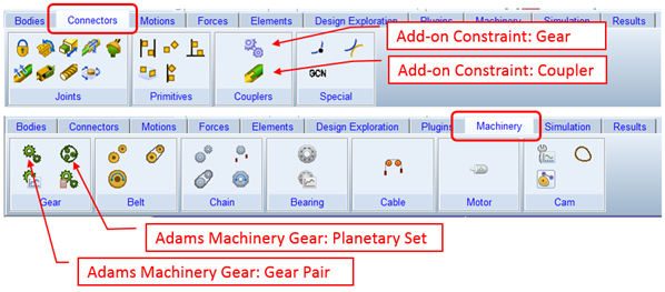
■Gear Constraint: An add-on constraint that adds idealized gear-like behavior between two parts already ideally connected to a common carrier part. See About Gears section for more details.
■Coupler Constraint: An add-on constraint that will constrain the motion in one or two ideal joints to follow the motion of another at a prescribed ratio. See Couplers section for more details.
Adams Machinery Gear
Overall this module provides modeling automation to build gear pair geometry, parts, constraints and forces. There are multiple modeling methodology options with varying coverage for cylindrical (spur and helical), bevel (straight and spiral), hypoid, worm and rack/pinion pairs as well as planetary sets. Learn more about Adams Machinery Gear at Welcome to Adams Machinery Gear section. A very brief summary of the modeling methods follows below:
■Coupler Method (spur gear only): This is a simple method used to transmit the velocity through a gear ratio. This method is used when forces and components involved in it are neglected and only speed reduction or multiplication is of interest. For more details see the Couplers documentation and the Adams Machinery Gear dialog box help pages.
■Simplified Method: This method calculates the gear forces and backlash between the gear pair analytically. It is useful when friction is neglected. The contact force calculation is fast because of its analytical approach. Some small out of plane motion is possible for cylindrical gears. For more details see Simplified Gear Method and the Adams Machinery Gear dialog box help pages.
■Detailed Method (spur gear only): This method calculates the contact forces between the gear pair analytically using an involute function and user defined contact properties. It can calculate contact up to three teeth at a time to capture variation of loading. It is useful when friction is considered. No out of plane motion is captured. For more details see Detailed Spur Gear Method and the Adams Machinery Gear dialog box help pages.
■3D Contact: This method uses geometry-based shell-to-shell contact. It calculates true backlash based on actual working distance and tooth thickness. It allows for consideration of any out-of-plane motions within the gear pair. For more details see 3D Contact Gear Method and the Adams Machinery Gear dialog box help pages.
■Advanced 3D Contact (cylindrical gears only): This method employs a fully automated finite element analysis pre-processing to derive gear tooth compliance for the Adams analysis. It therefore provides a representation of tooth flexibility whereas other methods treat the gear teeth rigidly. It also allows for out of plane motion of the gears. For more details see Advanced 3D Contact Gear and the Adams Machinery Gear dialog box help pages.
Adams Car
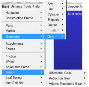
■Geometry - Gear: This creates a simple bi-colored disc-like geometry to apply to a rotating part that's to be treated somehow as a gear via some of the means described below. See Create/Modify Gear Geometry for more details.
■Differential Gear: Employs an add-on constraint to constrain the motion in one or two ideal joints to follow the motion of another at a prescribed ratio. See Gears for more details.
■Reduction Gear: Employs an add-on constraint to constrain the motion in one ideal joint to follow the motion of another at a ratio either prescribed directly by the user or inferred based on the affected parts' geometry. See Gears for more details.
■Machinery Gear: This is the access point within Adams Car for the Adams Machinery Gear modeling methods. See Adams Machinery Gear above, for details.
Adams Driveline
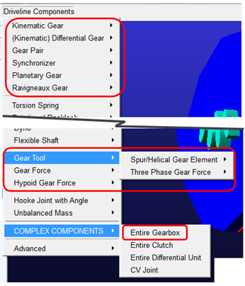
■Gear Pair: This creates a force between two parts with "Geometry - Gear" style geometry. A user-entered angular backlash defines the freeplay between the two parts. One this has been taken up a resistance torque is applied based on stiffness, damping and a sharpness factor which defines how quickly the resistance torque is applied. No out-of-plane motion or friction is represented. See Gear Pairs for details.
■Synchronizer: This works with gears modeled via the Adams Driveline Gear Pair component described above. It represents a clutch that brings a gear and shaft to the same rotational speed. See Synchronizers for details.
■Planetary Gear: This is a conceptual model (that is, no actual planet parts) of a planetary gear set. A user-entered angular backlash defines the freeplay between each of the constituent gear pairs. Two options exist for the reaction torque that's applied once the backlash is taken up: a stiffness/damping/sharpness style like used in the Gear Pair, or a BISTOP function based style. No out-of-plane motion or friction is represented. See Planetary Gears for details.
■Ravigneaux Gear: This is a conceptual model (that is, no actual planet parts) of a Ravigneaux gear set. A user-entered angular backlash defines the freeplay between each of the constituent gear pairs. Two options exist for the reaction torque that's applied once the backlash is taken up: a stiffness/damping/sharpness style like used in the Gear Pair, or a BISTOP function based style. No out-of-plane motion or friction is represented. See Ravigneaux Gears for details.
■Gear Tool
♦Spur/Helical Gear Element: Creates a single gear part with involute-like geometry. For more details see Gear and the dialog box help for this item.
♦Three Phase Gear Force: Creates a force between two Spur/Helical Gear Elements. The force has an inactive phase while backlash is taken up followed by an oil compression phase which employs one stiffness and damping curve, then a structural stiffness phase applying a different stiffness and damping rate. See Three-Phase Gear Force for more details.
■Gear Force: This creates a spur or bevel gear-like force between any two parts (that is, not necessarily those with "Geometry - Gear" style geometry). A user-entered angular backlash defines the freeplay between the two parts. One this has been taken up a resistance torque is applied based on stiffness, damping and a sharpness factor which defines how quickly the resistance torque is applied. See Gear Forces for details.
■Hypoid Gear Force: This creates hypoid gear-like force between any two parts (that is, not necessarily those with "Geometry - Gear" style geometry). The forces between the pinion and gear are based on user-entered stiffness and damping and a set of geometric characteristics specified in a property file. See Hypoid Gear Forces for details.
■COMPLEX COMPONENTS
♦Entire Gearbox: This is used to launch modeling automation to create a set of 1 or 2 shafts, parts (that is, gears, including Geometry - Gear style geometry) and Gear Pairs to define a 5 or 6 speed gearbox. See the Gearbox Assembly dialog box help for details.