Idealized Joints
About Idealized Joints
Idealized joints connect two parts. The parts can be rigid bodies, Flexible bodies, or Point masses. You can place idealized joints anywhere in your model.
Note: | The joints you can attach to flexible bodies depend on the version of Adams Solver you are using (C++ or FORTRAN). In addition, Adams Solver (C++) does not support point masses. For a summary of which joints and forces are supported on flexible bodies, see Table of Supported Forces and Joints in the Adams Flex online help. Also refer to the Adams Flex online help for more information on attaching joints and forces to flexible bodies. |
Adams View supports two types of idealized joints: simple and complex. Simple joints directly connect bodies and include the following:
■Revolute Joints. See Revolute Joint Tool.
■Translational Joints. See Translational Joint Tool.
■Cylindrical Joints. See Cylindrical Joint Tool.
■Spherical Joints. See Spherical Joint Tool.
■Planar Joints. See Planar Joint Tool.
■Constant-Velocity Joints. See Constant-Velocity Joint Tool.
■Screw Joints. See Screw Joint Tool.
■Fixed Joints. See Fixed Joint Tool.
■Hooke/Universal Joint. See Hooke/Universal Joint Tool.
Complex joints indirectly connect parts by coupling simple joints. They include:
■Gears. See Gear Joint Tool.
■Couplers. See Coupler Joint Tool.
You access the joints through the Joint Palette and Joint and Motion Tool Stacks.
Creating Idealized Joints
The following procedure explains how to create a simple idealized joint. You can select to attach the joint to parts or spline curves. If you select to attach the joint to a curve, Adams View creates a curve marker, and the joint follows the line of the curve. Learn more about curve markers with Marker Modify dialog box help. Attaching the joint to a spline curve is only available with Adams Solver (C++). Learn about switching solvers with Solver Settings - Executable dialog box help.
Note that this procedure only sets the location and orientation of the joint. If you want to set the friction of a joint, change the pitch of a screw joint, or set initial conditions for joints, modify the joint.
To create a simple idealized joint:
1. From the Joint palette or tool stack, select the joint tool representing the idealized joint that you want to create.
2. In the settings container, specify how you want to define the bodies the joint connects. You can select:
♦1 Location (Bodies Implicit)
♦2 Bodies - 1 Location
♦2 Bodies - 2 Locations
For more on the effects of these options, see the help for the joint tool you are creating and Connecting Constraints to Parts.
3. In the settings container, specify how you want the joint oriented. You can select:
♦Normal to Grid - Lets you orient the joint along the current Working grid, if it is displayed, or normal to the screen.
♦Pick Geometry Feature - Lets you orient the joint along a direction vector on a feature in your model, such as the face of a part.
4. If you selected to explicitly define the bodies by selecting 2 Bodies - 1 Location or 2 Bodies - 2 Locations in Step 2, in the settings container, set First Body and Second Body to how you want to attach the joint: on the bodies of parts, between a part and a spline curve, or between two spline curves.
5. Using the left mouse button, select the first part or a spline curve (splines and data element curves are all considered curves). If you selected to explicitly select the parts to be connected, select the second part or another curve using the left mouse button.
6. Place the cursor where you want the joint to be located (for a curve this is referred to as its curve point), and click the left mouse button. If you selected to specify its location on each part or curve, place the cursor on the second location, and click the left mouse button.
7. If you selected to orient the joint along a direction vector on a feature, move the cursor around in your model to display an arrow representing the direction along a feature where you want the joint oriented. When the direction vector represents the correct orientation, click the left mouse button.
Modifying Basic Properties of Idealized Joints
You can change several basic properties about an Idealized joints. These include:
■Parts that the joint connects. You can also switch which part moves relative to another part.
■What type of joint it is. For example, you can change a revolute joint to a translational joint. The following are exceptions to changing a joint's type:
♦You can only change a simple idealized joint to another type of simple idealized joint or to a joint primitive.
♦You cannot change a joint's type if motion is applied to the joint. In addition, if a joint has friction and you change the joint type, Adams View displays an error.
■Whether or not forces that are applied to the parts connected by the joint appear graphically on the screen during an animation. Learn about Setting Up Force Graphics.
■For a screw joint, you can also set the pitch of the threads of the screw (translational displacement for every full rotational cycle). Learn about screw joints.
To change basic properties for a joint:
2. If desired, in the First Body and Second Body text boxes, change the parts that the joint connects. The part that you enter as the first body moves relative to the part you enter as the second body.
3. Set Type to the type of joint to which you want to change the current joint.
4. Select whether you want to display force graphics for one of the parts that the joint connects.
5. For a screw joint, enter its pitch value (translational displacement for every full rotational cycle).
6. Select OK.
About Initial Conditions for Joints
You can specify initial conditions for revolute, translational, and cylindrical joints. Adams View uses the initial conditions during an Initial conditions simulation, which it runs before it runs a simulation of your model.
You can specify the following initial conditions for revolute, translational, and cylindrical joints:
■Translational or rotational displacements that define the translation of the location of the joint on the first part (I marker) with respect to its location on the second part (J marker) in units of length. You can set translational displacement on a translational and cylindrical joint and you can set rotational displacements on a revolute and cylindrical joint.
Adams View measures the translational displacement at the origin of the I marker along the common z-axis of the I and J markers and with respect to the J marker. It measures the rotational displacement of the x-axis of the I marker about the common z-axis of the I and J markers with respect to the x-axis of the J marker.
■Translational or rotational velocity that define the velocity of the location of the joint on the first part (I marker) with respect to its location on the second part (J marker) in units of length per unit of time.
Adams View measures the translational velocity of the I marker along the common z-axis of I and J and with respect to the J marker. It measures the rotational velocity of the x-axis of the I marker about the common z-axis of the I and J markers with respect to the x-axis of the J marker.
If you specify initial conditions, Adams View uses them as the initial velocity of the joint during an assemble model operation regardless of any other forces acting on the joint. You can also leave some or all of the initial conditions unset. Leaving an initial condition unset lets Adams View calculate the conditions of the part during an assemble model operation depending on the other forces acting on the joint. Note that it is not the same as setting an initial condition to zero. Setting an initial condition to zero means that the joint will not be moving in the specified direction or will not be displaced when the model is assembled, regardless of any forces acting on it.
If you impose initial conditions on the joint that are inconsistent with those on a part that the joint connects, the initial conditions on the joint have precedence over those on the part. If, however, you impose initial conditions on the joint that are inconsistent with imparted motions on the joint, the initial conditions as specified by the motion generator take precedence over those on the joint.
Setting Initial Conditions
To modify initial conditions:
2. Select Initial Conditions.
The Joint Initial Conditions dialog box appears. Some options in the Joint Initial Conditions dialog box are not available (ghosted) depending on the type of joint for which you are setting initial conditions.
3. Set the translational or rotational displacement or velocity, and then select OK.
Note: | If the initial rotational displacement of a revolute or cylindrical joint varies by anywhere from 5 to 60 degrees from the actual location of the joint, Adams Solver issues a warning message and continues execution. If the variation is greater than 60 degrees, Adams View issues an error message and stops execution. |
Imposing Point Motion on a Joint
You can impose a motion on any of the axes (DOF) of the idealized joint that are free to move. For example, for a translational joint, you can apply translational motion along the z-axis. Learn more About Point Motion.
Note: | For translational, revolute, and cylindrical joints, you might find it easier to use the joint motion tools to impose motion. Learn about Creating Point Motions Using the Motion Tools. |
To impose motion on a joint:
2. Select Impose Motion.
The Impose Motion(s) dialog box appears. Some options in the Impose Motion dialog box are not available (ghosted) depending on the type of joint on which you are imposing motion.
3. Enter a name for the motion. Adams View assigns a default name to the motion.
4. Enter the values for the motion as explained in Options for Point Motion Dialog Box, and then select OK.
Adding Friction to Idealized Joints
You can model both static (Coulomb) and dynamic (viscous) friction in revolute, translational, cylindrical, hooke/universal, and spherical joints.
Note: | Using Adams Solver (C++), you can apply joint friction to joints if they are attached to flexible bodies; using Adams Solver (FORTRAN), you cannot. In addition, Adams Solver (C++) does not support point masses. For a summary of which joints and forces are supported on flexible bodies, see Table of Supported Forces and Joints in the Adams Flex online help. Also refer to the Adams Flex online help for more information on attaching joints and forces to flexible bodies. |
To add friction to a joint:
2. Select the Friction tool  .
.
. The Create/Modify Friction dialog box appears. The options in the dialog box change depending on the type of joint for which you are adding friction.
3. Enter the values in the dialog box for the type of joint as explained below, and then select OK.
Friction Regime Determination (FRD)
Three friction regimes are allowed in Adams View:
The regime: | Means: |
|---|---|
Dynamic friction | A joint is in dynamic friction if its joint velocity magnitude exceeds 1.5 times the stiction transition velocity. The dynamic coefficient of friction (md) is used in the computation of frictional forces. |
Transition between dynamic and static friction | If the joint velocity magnitude is between 1 and 1.5 times the stiction transition velocity, the joint is considered to be transitioning between static and dynamic friction. A STEP function transitions the coefficient of friction between the dynamic (md) and static (ms) coefficients of friction. |
Static friction | A joint is in static friction when the joint velocity magnitude falls below the stiction transition velocity. The effective coefficient of friction is computed using the joint creep, joint velocity, and static coefficient of friction ( ms ). |
The joint velocity determines the instantaneous friction regime for a joint. The following is a block diagram of the friction regimes available in Adams Solver.
LuGre Formulation
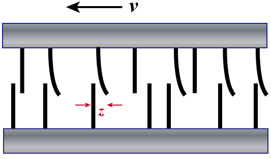
LuGre friction model is a type of state variable friction models, where extra state variables (internal states) are introduced to determine the level of friction. For LuGre friction model, the microscopic average bristle deflection z of the contact surface is adopted as the state variable. Therefore, the friction can be considered as the forces produced by the bending bristles. In 1D translational joint cases, the friction is given by
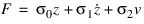 | (1) |
where  is the bristle stiffness,
  is the microscopic damping, and
  is the viscous friction coefficient. Notice that
  since z represents the average deflection rate of the bristle while v is the velocity of the contact body. To determine the value of z, an additional differential equation is used in the formulation
is the bristle stiffness, is the microscopic damping, and is the viscous friction coefficient. Notice that since z represents the average deflection rate of the bristle while v is the velocity of the contact body. To determine the value of z, an additional differential equation is used in the formulation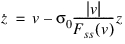 | (2) |
where
 | (3) |
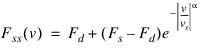
N is the normal contact force, Fs and Fd are the maximum static friction and dynamic friction,  and
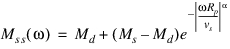
and  are dynamic and static frictional coefficients, respectively. Fss(v) represents the steady-state LuGre friction for a specific v, where
  and z=const.
and are dynamic and static frictional coefficients, respectively. Fss(v) represents the steady-state LuGre friction for a specific v, where and z=const. For 1D revolute joint cases, the frictional forces between the pin and hole result in the frictional torque, which is given by

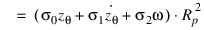 | (4) |
where Rp is the pin radius,  is the angular displacement,
  . Based on Eq. (2), the additional differential equation is obtained as
is the angular displacement, . Based on Eq. (2), the additional differential equation is obtained as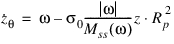 | (5) |
where
 | (6) |
 represents the steady-state LuGre frictional torque for a specific
  , where
  and
and  =const.
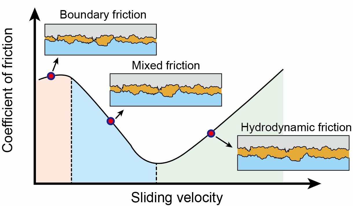
In the cases where only dry friction is considered,  , which determines whether viscous friction is considered in the model, should be zero. Stribeck velocity vs is always small and is used to determine the range of Stribeck effect. Stribeck effect decay exponent
  is used to determine the decay speed (the shape of Stribeck effect curve), as shown in above figure. Different
  values between 0.5 and 2 are recommended in the literature, and
  =2 is the default in Adams.
, which determines whether viscous friction is considered in the model, should be zero. Stribeck velocity vs is always small and is used to determine the range of Stribeck effect. Stribeck effect decay exponent is used to determine the decay speed (the shape of Stribeck effect curve), as shown in above figure. Different values between 0.5 and 2 are recommended in the literature, and =2 is the default in Adams.Conventions in Friction Block Diagrams
The following tables identify conventions used in the block diagrams:
■Legend for Block Diagrams identifies symbols in the diagrams.
■Relationship Between the Inputs Option and Switches Used in the Block Diagrams describes the relationship between the Input Forces to Friction option in the Create/Modify Friction dialog box and the switches used in the block diagrams.
Legend for Block Diagrams
Symbol: | Description: |
|---|---|
 | Scalar quantity |
 | Vector quantity |
 | Summing junction: c=a+b |
 | Multiplication junction: c=axb |
MAG | Magnitude of a vector quantity |
ABS | Absolute value of a scalar quantity |
FRD | Friction regime determination |
Relationship Between the Inputs Option and Switches Used in the Block Diagrams
Switch: | Inputs are: | Symbol: | Acceptable values: |
|---|---|---|---|
SW1 | Preload | Fprfrc or Tprfc | On or off |
SW2 | Reaction force | f or F | On or off |
SW3 | Bending moment | Tr | On or off |
SW4 | Torsional moment | Tn | On or off |
All or None sets all applicable switches On or off, respectively | |||
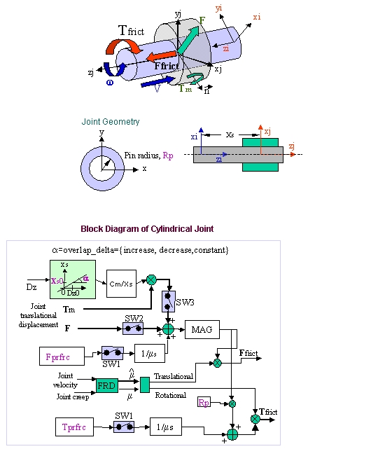
Cylindrical Joint friction
Joint reaction (F) and reaction torque (Tm) combined with force preload (Fprfrc) and torque preload (Tprfrc) yield the frictional force and torque in a cylindrical joint. Notice that Tm multiplies Cm/Xs where Cm stands for the BENDING_FACTOR. Cm was equal to 1.0 in releases previous to 2018. As the block diagram indicates, you can turn off one or more of these force effects using switches SW1 through SW3. The frictional force in a cylindrical joint acts at the mating surfaces of the joint. The FRD block determines the direction of the frictional force. Based on the frictional coefficient direction, the surface frictional force is broken down into an equivalent frictional torque and frictional force acting along the common axis of translation and rotation.
Cylindrical Joint Options
For the option: | Do the following: |
|---|---|
Mu Static | Define the coefficient of static friction in the joint. The magnitude of the frictional force is the product of Mu Static and the magnitude of the normal force in the joint, for example: Friction Force Magnitude, F = µN where µ = Mu Static and N = normal force The static frictional force acts to oppose the net force or torque along the Degrees of freedom of the joint. The range is > 0. |
Mu Dynamic | Define the coefficient of dynamic friction. The magnitude of the frictional force is the product of Mu Dynamic and the magnitude of the normal force in the joint, for example: Friction force magnitude, F = µN where µ = Mu Dynamic and N = normal force The dynamic frictional force acts in the opposite direction of the velocity of the joint. The range is > 0. |
Initial Overlap | Defines the initial overlap of the sliding parts in either a translational or cylindrical joint. The joint's bending moment is divided by the overlap to compute the bending moment's contribution to frictional forces. The default is 1000.0, and the range is Initial Overlap > 0. |
Overlap | To define friction in a cylindrical joint, Adams Solver computes the overlap of the joint. As the joint slides, the overlap can increase, decrease, or remain constant. You can set: ■Increase indicates that overlap increases as the I marker translates in the positive direction along the J marker; the slider moves to be within the joint. ■Decrease indicates that the overlap decreases with positive translation of the joint; the slider moves outside of the joint. ■Remain Constant indicates that the amount of overlap does not change as the joint slides; all of the slider remains within the joint. The default is Remain Constant. |
Pin Radius | Defines the radius of the pin for a cylindrical joint. The default is 1.0, and the range is > 0. |
Bending Factor | Defines the coefficient that multiplies the term Tm/Xs when the input is used for the friction force computation. The default is 1.0, and the range is > 0. |
Stiction Transition Velocity | Define the absolute velocity threshold for the transition from dynamic friction to static friction. If the absolute relative velocity of the joint marker is below the value, then static friction or stiction acts to make the joint stick. The default is 0.1 length units/unit time on the surface of contact in the joint, and the range is > 0. |
Transition Velocity Coefficient | Defines the absolute velocity threshold for the transition from static friction to dynamic friction. If the absolute relative velocity of the joint marker is at or above TRANSITION_VELOCITY_COEFFICIENT * STICTION_TRANSITION_VELOCITY, then the dynamic friction coefficient is applied. Between STICTION_TRANSITION_VELOCITY and TRANSITION_VELOCITY_COEFFICIENT * STICTION_TRANSITION_VELOCITY the coefficient of friction is transitioning from the static coefficient of friction to the dynamic coefficient of friction. Default: 1.5 Range: TRANSITION_VELOCITY_COEFFICIENT > 1 |
Max Stiction Deformation | Define the maximum displacement that can occur in a joint once the frictional force in the joint enters the stiction regime. The slight deformation allows Adams Solver to easily impose the Coulomb conditions for stiction or static friction, for example: Friction force magnitude < static * normal force Therefore, even at zero velocity, you can apply a finite stiction force if your system dynamics require it. The default is 0.01 length units, and the range is > 0. |
Friction Force Preload | Define the joint's preload frictional force, which is usually caused by mechanical interference in the assembly of the joint. Default is 0.0, and the range is > 0. |
Friction Torque Preload | Define the preload friction torque in the joint, which is usually caused by mechanical interference in the assembly of the joint. The default is 0.0, and the Range is > 0. |
Max Friction Force | The maximum friction force value sets an upper limit to how much friction force will be applied regardless what the actual friction calculation based on load and coefficient would apply. Leaving this field blank will apply the default value of 1E25 (the field maximum). |
Max Friction Torque | The maximum friction torque value sets an upper limit to how much friction torque will be applied regardless what the actual friction calculation based on load and coefficient would apply. Leaving this field blank will apply the default value of 1E25 (the field maximum). |
Effect | Define the frictional effects included in the friction model, either Stiction and Sliding, Stiction, or Sliding. Stiction is static-friction effect, while Sliding is dynamic-friction effect. Excluding stiction in simulations that don't require it can greatly improve simulation speed. The default is Stiction and Sliding. |
Input Forces to Friction | Define the input forces to the friction model. By default, all user-defined preloads and joint-reaction force and moments are included. You can customize the friction-force model by limiting the input forces you specify. The inputs for a translational joint are: ■Preload ■Reaction Force ■Bending Moment |
Friction Inactive During | Specify whether or not the frictional forces are to be calculated during a Static equilibrium or Quasi-static simulation. |
Formulation | Defines the formulation that Adams uses to calculate the frictional force. Default: original |
Bristle Stiffness Coefficient | Defines the stiffness coefficient of the bristle and is the coefficient  in the LuGre formulation. in the LuGre formulation.Default: 1e4 Range: BRISTLE_STIFFNESS_COEFFICIENT > 0 |
Damping Coefficient | Defines the damping coefficient in the rate of microscopic deflection and is the coefficient  in the LuGre formulation in the LuGre formulationDefault: 1e2 Range: DAMPING_COEFFICIENT >= 0 |
Viscous Friction Coefficient | Defines the damping coefficient of the viscous component of the friction force and is the coefficient  in the LuGre formulation in the LuGre formulationDefault: 0 Range: VISCOUS_FRICTION_COEFFICIENT >= 0 |
Velocity Threshold Stribeck | Defines the threshold of the Stribeck velocity and is the vs component in the LuGre formulation Default: 1e-3 Range: VELOCITY_THRESHOLD_STRIBECK > 0 |
Decay Exponent Stribeck | Defines the exponent of the Stribeck friction decay and is the  component in the LuGre formulation component in the LuGre formulationDefault: 2 Range: DECAY_EXPONENT_STRIBECK > 0 |
Revolute Joint Friction
Joint reactions (Fa and Fr), bending moment (Tr), and torque preload (Tprfrc) determine the frictional torque in a revolute joint. You can turn off one or more of these force effects using switches SW1 through SW3. The joint reactions (Fa and Fr) are converted into equivalent torques using the respective friction arm (Rn) and pin radius (Rp). The joint bending moment (Tr) is converted into an equivalent torque using pin radius (Rp) divided by bending reaction arm (Rb). The frictional torque (Tfrict) is applied along the axis of rotation in the direction that the FRD block computes.
Revolute Joint Options
For the option: | Do the following: |
|---|---|
Mu Static | Define the coefficient of static friction in the joint. The magnitude of the frictional force is the product of Mu Static and the magnitude of the normal force in the joint, for example: Friction Force Magnitude, F = µN where µ = Mu Static and N = normal force The static frictional force acts to oppose the net force or torque along the Degrees of freedom of the joint. The range is > 0. |
Mu Dynamic | Define the coefficient of dynamic friction. The magnitude of the frictional force is the product of Mu Dynamic and the magnitude of the normal force in the joint, for example: Friction force magnitude, F = µN where µ = Mu Dynamic and N = normal force The dynamic frictional force acts in the opposite direction of the velocity of the joint. The range is > 0. |
Friction Arm | Define the effective moment arm used to compute the axial component of the friction torque. The default is 1.0, and the range is > 0. |
Bending Reaction Arm | Define the effective moment arm use to compute the contribution of the bending moment on the net friction torque in the revolute joint. Is defined as the distance between the reaction forces. The default is 1.0, and the range is > 0. |
Pin Radius | Defines the radius of the pin. The default is 1.0, and the range is > 0. |
Stiction Transition Velocity | Define the absolute velocity threshold for the transition from dynamic friction to static friction. If the absolute relative velocity of the joint marker is below the value, then static friction or stiction acts to make the joint stick. The default is 0.1 length units/unit time on the surface of contact in the joint, and the range is > 0. |
Transition Velocity Coefficient | Defines the absolute velocity threshold for the transition from static friction to dynamic friction. If the absolute relative velocity of the joint marker is at or above TRANSITION_VELOCITY_COEFFICIENT * STICTION_TRANSITION_VELOCITY, then the dynamic friction coefficient is applied. Between STICTION_TRANSITION_VELOCITY and TRANSITION_VELOCITY_COEFFICIENT * STICTION_TRANSITION_VELOCITY the coefficient of friction is transitioning from the static coefficient of friction to the dynamic coefficient of friction. Default: 1.5 Range: TRANSITION_VELOCITY_COEFFICIENT > 1 |
Max Stiction Deformation | Define the maximum displacement that can occur in a joint once the frictional force in the joint enters the stiction regime. The slight deformation allows Adams Solver to easily impose the Coulomb conditions for stiction or static friction, for example: Friction force magnitude < static * normal force Therefore, even at zero velocity, you can apply a finite stiction force if your system dynamics require it. The default is 0.01 length units, and the range is > 0. |
Friction Torque Preload | Define the preload friction torque in the joint, which is usually caused by mechanical interference in the assembly of the joint. The default is 0.0, and the Range is > 0. |
Max Friction Torque | The maximum friction torque value sets an upper limit to how much friction torque will be applied regardless what the actual friction calculation based on load and coefficient would apply. Leaving this field blank will apply the default value of 1E25 (the field maximum). |
Effect | Define the frictional effects included in the friction model, either Stiction and Sliding, Stiction, or Sliding. Stiction is static-friction effect, while Sliding is dynamic-friction effect. Excluding stiction in simulations that don't require it can greatly improve simulation speed. The default is Stiction and Sliding. |
Input Forces to Friction | Define the input forces to the friction model. By default, all user-defined preloads and joint-reaction force and moments are included. You can customize the friction-force model by limiting the input forces you specify. The inputs for a translational joint are: ■Preload ■Reaction Force ■Bending Moment |
Friction Inactive During | Specify whether or not the frictional forces are to be calculated during a Static equilibrium or Quasi-static simulation. |
Formulation | Defines the formulation that Adams uses to calculate the frictional force. Default: original |
Bristle Stiffness Coefficient | Defines the stiffness coefficient of the bristle and is the coefficient  in the LuGre formulation. in the LuGre formulation.Default: 1e4 Range: BRISTLE_STIFFNESS_COEFFICIENT > 0 |
Damping Coefficient | Defines the damping coefficient in the rate of microscopic deflection and is the coefficient  in the LuGre formulation in the LuGre formulationDefault: 1e2 Range: DAMPING_COEFFICIENT >= 0 |
Viscous Friction Coefficient | Defines the damping coefficient of the viscous component of the friction force and is the coefficient  in the LuGre formulation in the LuGre formulationDefault: 0 Range: VISCOUS_FRICTION_COEFFICIENT >= 0 |
Velocity Threshold Stribeck | Defines the threshold of the Stribeck velocity and is the vs component in the LuGre formulation Default: 1e-3 Range: VELOCITY_THRESHOLD_STRIBECK > 0 |
Decay Exponent Stribeck | Defines the exponent of the Stribeck friction decay and is the  component in the LuGre formulation component in the LuGre formulationDefault: 2 Range: DECAY_EXPONENT_STRIBECK > 0 |
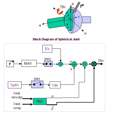
Spherical Joint Friction
The reaction force (F) and the preload frictional torque (Tprfrc) are the two forcing effects used in computing the frictional torque on a Spherical joint. The ball radius is used to compute an equivalent frictional torque. The FRD block determines the direction of the frictional torque.
Spherical Joint Options
For the option: | Do the following: |
|---|---|
Mu Static | Define the coefficient of static friction in the joint. The magnitude of the frictional force is the product of Mu Static and the magnitude of the normal force in the joint, for example: Friction Force Magnitude, F = µN where µ = Mu Static and N = normal force The static frictional force acts to oppose the net force or torque along the Degrees of freedom of the joint. The range is > 0. |
Mu Dynamic | Define the coefficient of dynamic friction. The magnitude of the frictional force is the product of Mu Dynamic and the magnitude of the normal force in the joint, for example: Friction force magnitude, F = µN where µ = Mu Dynamic and N = normal force The dynamic frictional force acts in the opposite direction of the velocity of the joint. The range is > 0. |
Ball Radius | Defines the radius of the ball in a spherical joint for use in friction-force and torque calculations. The default is 1.0, and the range is > 0. |
Stiction Transition Velocity | Define the absolute velocity threshold for the transition from dynamic friction to static friction. If the absolute relative velocity of the joint marker is below the value, then static friction or stiction acts to make the joint stick. The default is 0.1 length units/unit time on the surface of contact in the joint, and the range is > 0. |
Transition Velocity Coefficient | Defines the absolute velocity threshold for the transition from static friction to dynamic friction. If the absolute relative velocity of the joint marker is at or above TRANSITION_VELOCITY_COEFFICIENT * STICTION_TRANSITION_VELOCITY, then the dynamic friction coefficient is applied. Between STICTION_TRANSITION_VELOCITY and TRANSITION_VELOCITY_COEFFICIENT * STICTION_TRANSITION_VELOCITY the coefficient of friction is transitioning from the static coefficient of friction to the dynamic coefficient of friction. Default: 1.5 Range: TRANSITION_VELOCITY_COEFFICIENT > 1 |
Max Stiction Deformation | Define the maximum displacement that can occur in a joint once the frictional force in the joint enters the stiction regime. The slight deformation allows Adams Solver to easily impose the Coulomb conditions for stiction or static friction, for example: Friction force magnitude < static * normal force Therefore, even at zero velocity, you can apply a finite stiction force if your system dynamics require it. The default is 0.01 length units, and the range is > 0. |
Friction Torque Preload | Define the preload friction torque in the joint, which is usually caused by mechanical interference in the assembly of the joint. The default is 0.0, and the Range is > 0. |
Max Friction Torque | The maximum friction torque value sets an upper limit to how much friction torque will be applied regardless what the actual friction calculation based on load and coefficient would apply. Leaving this field blank will apply the default value of 1E25 (the field maximum). |
Effect | Define the frictional effects included in the friction model, either Stiction and Sliding, Stiction, or Sliding. Stiction is static-friction effect, while Sliding is dynamic-friction effect. Excluding stiction in simulations that don't require it can greatly improve simulation speed. The default is Stiction and Sliding. |
Input Forces to Friction | Define the input forces to the friction model. By default, all user-defined preloads and joint-reaction force and moments are included. You can customize the friction-force model by limiting the input forces you specify. The inputs for a translational joint are: ■Preload ■Reaction Force |
Friction Inactive During | Specify whether or not the frictional forces are to be calculated during a Static equilibrium or Quasi-static simulation. |
Formulation | Defines the formulation that Adams uses to calculate the frictional force. Default: original |
Bristle Stiffness Coefficient | Defines the stiffness coefficient of the bristle and is the coefficient  in the LuGre formulation. in the LuGre formulation.Default: 1e4 Range: BRISTLE_STIFFNESS_COEFFICIENT > 0 |
Damping Coefficient | Defines the damping coefficient in the rate of microscopic deflection and is the coefficient  in the LuGre formulation in the LuGre formulationDefault: 1e2 Range: DAMPING_COEFFICIENT >= 0 |
Viscous Friction Coefficient | Defines the damping coefficient of the viscous component of the friction force and is the coefficient  in the LuGre formulation in the LuGre formulationDefault: 0 Range: VISCOUS_FRICTION_COEFFICIENT >= 0 |
Velocity Threshold Stribeck | Defines the threshold of the Stribeck velocity and is the vs component in the LuGre formulation Default: 1e-3 Range: VELOCITY_THRESHOLD_STRIBECK > 0 |
Decay Exponent Stribeck | Defines the exponent of the Stribeck friction decay and is the  component in the LuGre formulation component in the LuGre formulationDefault: 2 Range: DECAY_EXPONENT_STRIBECK > 0 |
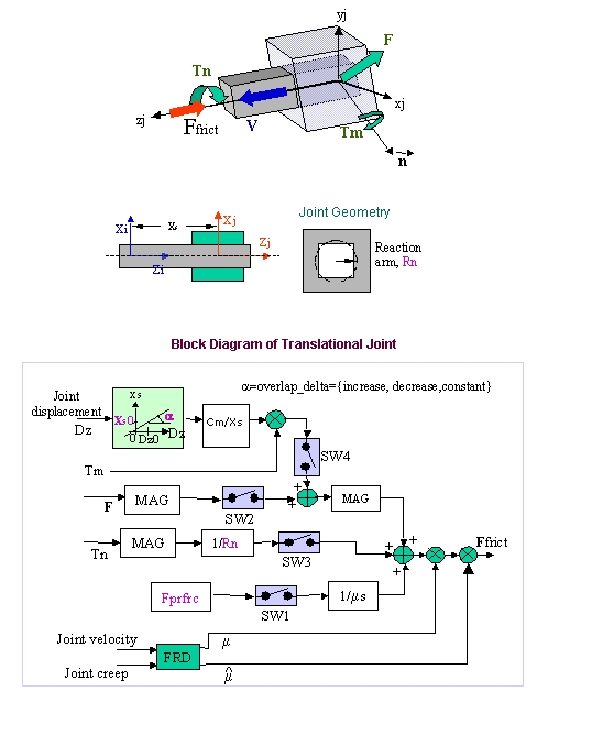
Translational Joint Friction
Joint reaction force (F), bending moment (Tm), torsional moment (Tn), and force preload (Fprfrc) are used to compute the frictional force in a translational joint. You can individually turn off the force effects using switches SW1 through SW4.
The bending moment (Tm) is converted into an equivalent force using the Cm/Xs block where Cm stands for the BENDING_FACTOR. Cm was equal to 1.0 in releases previous to 2018. Similarly, torsional moment is converted into an equivalent joint force using the friction arm (Rn). Frictional force (Ffrict) is applied along the axis of translation in the direction that the FRD block computes.
Translational Joint Options
For the option: | Do the following: |
|---|---|
Mu Static | Define the coefficient of static friction in the joint. The magnitude of the frictional force is the product of Mu Static and the magnitude of the normal force in the joint, for example: Friction Force Magnitude, F = µN where µ = Mu Static and N = normal force The static frictional force acts to oppose the net force or torque along the Degrees of freedom of the joint. The range is > 0. |
Mu Dynamic | Define the coefficient of dynamic friction. The magnitude of the frictional force is the product of Mu Dynamic and the magnitude of the normal force in the joint, for example: Friction force magnitude, F = µN where µ = Mu Dynamic and N = normal force The dynamic frictional force acts in the opposite direction of the velocity of the joint. The range is > 0. |
Reaction Arm | Define the effective moment arm of the joint-reaction torque about the translational joint's axial axis (the z-direction of the joint's J marker). This value is used to compute the contribution of the torsional moment to the net frictional force. The default is 1.0, and the range is > 0. |
Initial Overlap | Defines the initial overlap of the sliding parts in either a translational or cylindrical joint. The joint's bending moment is divided by the overlap to compute the bending moment's contribution to frictional forces. The default is 1000.0, and the range is Initial Overlap > 0. |
Overlap | To define friction in a cylindrical joint, Adams Solver computes the overlap of the joint. As the joint slides, the overlap can increase, decrease, or remain constant. You can set: ■Increase indicates that overlap increases as the I marker translates in the positive direction along the J marker; the slider moves to be within the joint. ■Decrease indicates that the overlap decreases with positive translation of the joint; the slider moves outside of the joint. ■Remain Constant indicates that the amount of overlap does not change as the joint slides; all of the slider remains within the joint. The default is Remain Constant. |
Bending Factor | Defines the coefficient that multiplies the term Tm/Xs when the input is used for the friction force computation. The default is 1.0, and the range is > 0. |
Stiction Transition Velocity | Define the absolute velocity threshold for the transition from dynamic friction to static friction. If the absolute relative velocity of the joint marker is below the value, then static friction or stiction acts to make the joint stick. The default is 0.1 length units/unit time on the surface of contact in the joint, and the range is > 0. |
Transition Velocity Coefficient | Defines the absolute velocity threshold for the transition from static friction to dynamic friction. If the absolute relative velocity of the joint marker is at or above TRANSITION_VELOCITY_COEFFICIENT * STICTION_TRANSITION_VELOCITY, then the dynamic friction coefficient is applied. Between STICTION_TRANSITION_VELOCITY and TRANSITION_VELOCITY_COEFFICIENT * STICTION_TRANSITION_VELOCITY the coefficient of friction is transitioning from the static coefficient of friction to the dynamic coefficient of friction. Default: 1.5 Range: TRANSITION_VELOCITY_COEFFICIENT > 1 |
Max Stiction Deformation | Define the maximum displacement that can occur in a joint once the frictional force in the joint enters the stiction regime. The slight deformation allows Adams Solver to easily impose the Coulomb conditions for stiction or static friction, for example: Friction force magnitude < static * normal force Therefore, even at zero velocity, you can apply a finite stiction force if your system dynamics require it. The default is 0.01 length units, and the range is > 0. |
Friction Force Preload | Define the joint's preload frictional force, which is usually caused by mechanical interference in the assembly of the joint. Default is 0.0, and the range is > 0. |
Max Friction Force | The maximum friction force value sets an upper limit to how much friction force will be applied regardless what the actual friction calculation based on load and coefficient would apply. Leaving this field blank will apply the default value of 1E25 (the field maximum). |
Effect | Define the frictional effects included in the friction model, either Stiction and Sliding, Stiction, or Sliding. Stiction is static-friction effect, while Sliding is dynamic-friction effect. Excluding stiction in simulations that don't require it can greatly improve simulation speed. The default is Stiction and Sliding. |
Input Forces to Friction | Define the input forces to the friction model. By default, all user-defined preloads and joint-reaction force and moments are included. You can customize the friction-force model by limiting the input forces you specify. The inputs for a translational joint are: ■Preload ■Reaction Force ■Bending Moment ■Torsional Moment |
Friction Inactive During | Specify whether or not the frictional forces are to be calculated during a Static equilibrium or Quasi-static simulation. |
Formulation | Defines the formulation that Adams uses to calculate the frictional force. Default: original |
Bristle Stiffness Coefficient | Defines the stiffness coefficient of the bristle and is the coefficient  in the LuGre formulation. in the LuGre formulation.Default: 1e4 Range: BRISTLE_STIFFNESS_COEFFICIENT > 0 |
Damping Coefficient | Defines the damping coefficient in the rate of microscopic deflection and is the coefficient  in the LuGre formulation in the LuGre formulationDefault: 1e2 Range: DAMPING_COEFFICIENT >= 0 |
Viscous Friction Coefficient | Defines the damping coefficient of the viscous component of the friction force and is the coefficient  in the LuGre formulation in the LuGre formulationDefault: 0 Range: VISCOUS_FRICTION_COEFFICIENT >= 0 |
Velocity Threshold Stribeck | Defines the threshold of the Stribeck velocity and is the vs component in the LuGre formulation Default: 1e-3 Range: VELOCITY_THRESHOLD_STRIBECK > 0 |
Decay Exponent Stribeck | Defines the exponent of the Stribeck friction decay and is the  component in the LuGre formulation component in the LuGre formulationDefault: 2 Range: DECAY_EXPONENT_STRIBECK > 0 |
Universal/Hooke Joint Friction
The universal/hooke joint contains two yokes (I_YOKE and J_YOKE) that are modeled independently. An equivalent revolute joint represents each yoke. Frictional torques are applied along the axes of rotation of the two yokes.
Universal/Hooke Joint Options
For the option: | Do the following: |
|---|---|
Yoke | Select either to define the rotational constraint on which the friction acts. I Yoke identifies the yoke to the I marker's rotational constraint. J Yoke identifies the yoke to the J marker's rotational constraint. |
Mu Static | Define the coefficient of static friction in the joint. The magnitude of the frictional force is the product of Mu Static and the magnitude of the normal force in the joint, for example: Friction Force Magnitude, F = µN where µ = Mu Static and N = normal force The static frictional force acts to oppose the net force or torque along the Degrees of freedom of the joint. The range is > 0. |
Mu Dynamic | Define the coefficient of dynamic friction. The magnitude of the frictional force is the product of Mu Dynamic and the magnitude of the normal force in the joint, for example: Friction force magnitude, F = µN where µ = Mu Dynamic and N = normal force The dynamic frictional force acts in the opposite direction of the velocity of the joint. The range is > 0. |
Friction Arm | Define the effective moment arm used to compute the axial component of the friction torque. The default is 1.0, and the range is > 0. |
Bending Reaction Arm | Define the effective moment arm use to compute the contribution of the bending moment on the net friction torque in the universal/hooke joint. The default is 1.0, and the range is > 0. |
Pin Radius | Define the radius of the pin. The default is 1.0, and the range is > 0. |
Stiction Transition Velocity | Define the absolute velocity threshold for the transition from dynamic friction to static friction. If the absolute relative velocity of the joint marker is below the value, then static friction or stiction acts to make the joint stick. The default is 0.1 length units/unit time on the surface of contact in the joint, and the range is > 0. |
Transition Velocity Coefficient | Defines the absolute velocity threshold for the transition from static friction to dynamic friction. If the absolute relative velocity of the joint marker is at or above TRANSITION_VELOCITY_COEFFICIENT * STICTION_TRANSITION_VELOCITY, then the dynamic friction coefficient is applied. Between STICTION_TRANSITION_VELOCITY and TRANSITION_VELOCITY_COEFFICIENT * STICTION_TRANSITION_VELOCITY the coefficient of friction is transitioning from the static coefficient of friction to the dynamic coefficient of friction. Default: 1.5 Range: TRANSITION_VELOCITY_COEFFICIENT > 1 |
Max Stiction Deformation | Define the maximum displacement that can occur in a joint once the frictional force in the joint enters the stiction regime. The slight deformation allows Adams Solver to easily impose the Coulomb conditions for stiction or static friction, for example: Friction force magnitude < static * normal force Therefore, even at zero velocity, you can apply a finite stiction force if your system dynamics require it. The default is 0.01 length units, and the range is > 0. |
Friction Torque Preload | Define the preload friction torque in the joint, which is usually caused by mechanical interference in the assembly of the joint. Default is 0.0, and the range is > 0. |
Max Friction Torque | The maximum friction torque value sets an upper limit to how much friction torque will be applied regardless what the actual friction calculation based on load and coefficient would apply. Leaving this field blank will apply the default value of 1E25 (the field maximum). |
Effect | Define the frictional effects included in the friction model, either Stiction and Sliding, Stiction, or Sliding. Stiction is static-friction effect, while Sliding is dynamic-friction effect. Excluding stiction in simulations that don't require it can greatly improve simulation speed. The default is Stiction and Sliding. |
Input Forces to Friction | Define the input forces to the friction model. By default, all user-defined preloads and joint-reaction force and moments are included. You can customize the friction-force model by limiting the input forces you specify. The inputs for a translational joint are: ■Preload ■Reaction Force ■Bending Moment |
Friction Inactive During | Specify whether or not the frictional forces are to be calculated during a Static equilibrium or Quasi-static simulation. |
Formulation | Defines the formulation that Adams uses to calculate the frictional force. Default: original |
Bristle Stiffness Coefficient | Defines the stiffness coefficient of the bristle and is the coefficient  in the LuGre formulation. in the LuGre formulation.Default: 1e4 Range: BRISTLE_STIFFNESS_COEFFICIENT > 0 |
Damping Coefficient | Defines the damping coefficient in the rate of microscopic deflection and is the coefficient  in the LuGre formulation in the LuGre formulationDefault: 1e2 Range: DAMPING_COEFFICIENT >= 0 |
Viscous Friction Coefficient | Defines the damping coefficient of the viscous component of the friction force and is the coefficient  in the LuGre formulation in the LuGre formulationDefault: 0 Range: VISCOUS_FRICTION_COEFFICIENT >= 0 |
Velocity Threshold Stribeck | Defines the threshold of the Stribeck velocity and is the vs component in the LuGre formulation Default: 1e-3 Range: VELOCITY_THRESHOLD_STRIBECK > 0 |
Decay Exponent Stribeck | Defines the exponent of the Stribeck friction decay and is the  component in the LuGre formulation component in the LuGre formulationDefault: 2 Range: DECAY_EXPONENT_STRIBECK > 0 |
DOF Removed by Idealized Joints
The following table lists all of the idealized joints except screw, gear, and coupler joints. It does not contain screw joints because they couple one rotational and one translational degree of freedom and cannot be placed in any one of the categories in the table. The table does not contain gears and couplers because they connect joints rather than parts.